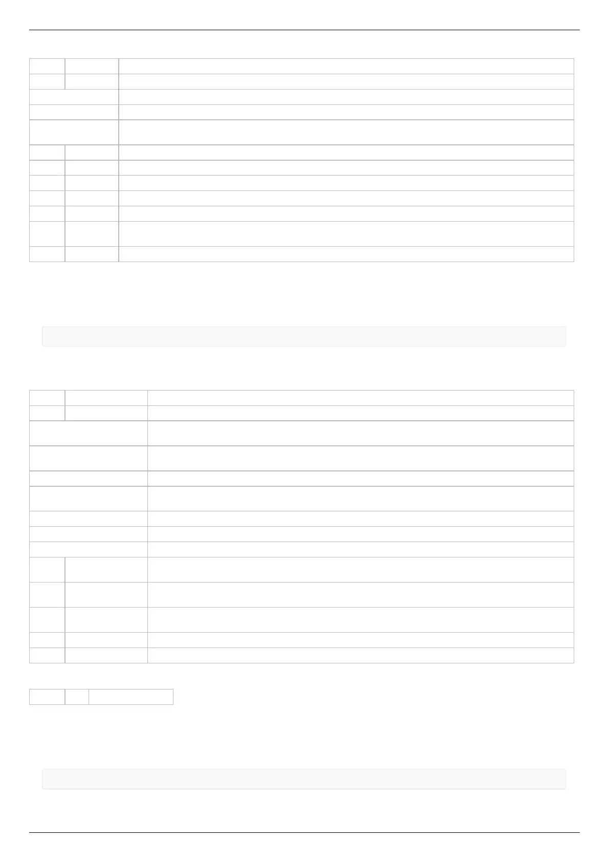
INT32U CMD Command (answer)
INT8U SyncInFlags Input synchronization flags
0x01 - SYNCIN_ENABLED (Synchronization in mode is enabled, if this flag is set.)
0x02 - SYNCIN_INVERT (Trigger on falling edge if flag is set, on rising edge otherwise.)
0x04 - SYNCIN_GOTOPOSITION (The engine is go to position specified in Position and uPosition, if this flag is
set. And it is shift on the Position and uPosition, if this flag is unset)
INT16U ClutterTime Input synchronization pulse dead time (mks).
INT32S Position Desired position or shift (whole steps)
INT16S uPosition The fractional part of a position or shift in microsteps. Is used with stepper motor. Range: -255..255.
INT32U Speed Target speed (for stepper motor: steps/s, for DC: rpm). Range: 0..100000.
INT8U uSpeed Target speed in microsteps/s. Using with stepper motor only.
INT8U
Reserved
[8]
Reserved (8 bytes)
INT16U CRC Checksum
Description:
Read input synchronization settings. This function fill structure with set of input synchronization settings, modes, periods and flags,
that specify behaviour of input synchronization. All boards are supplied with standard set of these settings.
Command SSNO
result_t set_sync_out_settings (device_t id, const sync_out_settings_t* sync_out_settings)
Command code (CMD): "ssno" or 0x6F6E7373.
Request: (16 bytes)
INT32U CMD Command
INT8U SyncOutFlags Output synchronization flags
0x01 - SYNCOUT_ENABLED (Synchronization out pin follows the synchronization logic, if set. It governed
by SYNCOUT_STATE flag otherwise.)
0x02 - SYNCOUT_STATE (When output state is fixed by negative SYNCOUT_ENABLED flag, the pin state
is in accordance with this flag state.)
0x04 - SYNCOUT_INVERT (Low level is active, if set, and high level is active otherwise.)
0x08 - SYNCOUT_IN_STEPS (Use motor steps/encoder pulses instead of milliseconds for output pulse
generation if the flag is set.)
0x10 - SYNCOUT_ONSTART (Generate synchronization pulse when movement starts.)
0x20 - SYNCOUT_ONSTOP (Generate synchronization pulse when movement stops.)
0x40 - SYNCOUT_ONPERIOD (Generate synchronization pulse every SyncOutPeriod encoder pulses.)
INT16U SyncOutPulseSteps
This value specifies duration of output pulse. It is measured microseconds when SYNCOUT_IN_STEPS
flag is cleared or in encoder pulses or motor steps when SYNCOUT_IN_STEPS is set.
INT16U SyncOutPeriod
This value specifies number of encoder pulses or steps between two output synchronization pulses when
SYNCOUT_ONPERIOD is set.
INT32U Accuracy
This is the neighborhood around the target coordinates, which is getting hit in the target position and
the momentum generated by the stop.
INT8U uAccuracy This is the neighborhood around the target coordinates in micro steps (only used with stepper motor).
INT16U CRC Checksum
Answer: (4 bytes)
INT32U CMD Command (answer)
Description:
Set output synchronization settings. This function send structure with set of output synchronization settings, that specify behaviour of
output synchronization, to controller's memory. All boards are supplied with standard set of these settings.
Command GSNO
result_t get_sync_out_settings (device_t id, sync_out_settings_t* sync_out_settings)