4.3.6. Revolution sensor
Revolution sensor is designed for stepper motor shutdown (failure) detection and for better accuracy of Home position calibration
procedure (see Automatic Home position calibration).
The controller may receive the actual position data from the external revolution sensor mounted on the stepper motor shaft. The
sensor transmits its signals to the controller once or many times per one revolution of the motor.
Usually the revolution sensor is a small disc with precise graduation scale mounted on the motor shaft. A light source (LED) and a
sensor of the optocoupler are placed at the opposite sides of the disc. The sensor is open if there is no interrupter between the LED
and the sensor (the logic zero is transmitted to optocoupler's output), whereas the logic one is transmitted if the light source is closed
by the interrupter.
By default, the lower logic level is interpreted by the controller as the active mode of the revolution sensor. The controller's input is
pulled to logic one level, thus, the disconnected revolution sensor means its inactive mode. The controller's input can be inverted if
necessary, in that case the logic one level will mean the active mode.
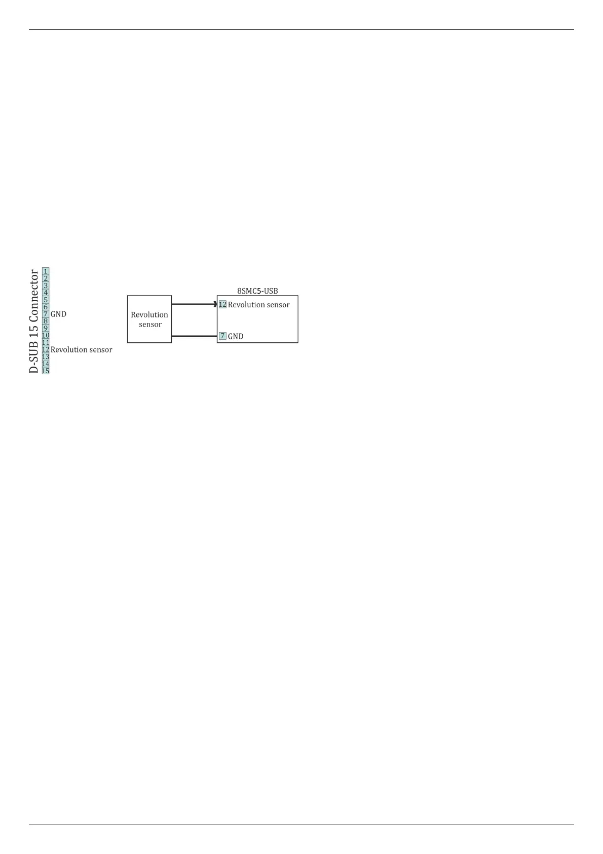
Connection diagram
The revolution sensor should be connected to the controller via 15pin D-SUB connector, which is in all systems ( controller board, one-
axis and two-axis in box).
Scheme of revolution sensor connection to the 8SMC5-USB based system