4.5.5. TTL synchronization
Principle of operation
TTL-synchronization is used to synchronize controller motion with external devices and/or events. For example, the controller can
output synchronization pulse each time it moves a certain distance. Vice versa, controller can shift a certain distance on incoming
synchronization pulse, for example from an experimental setup which is ready to move to the next measurement position.
To use mechanical contacts as an input synchronization signal a contact debouncing is provided. One can set minimum input pulse
length which is recognized as a valid synchronization signal. An active state is a logical one (see table 4.5.5.1), and a raising edge is
considered to be the start of a signal. However, if for some reason this is undesirable, both options may be inverted independently.
Type TTL
Logic zero level 0 V
Logic one level 3.3 V
Table 4.5.5.1 - Input parameters
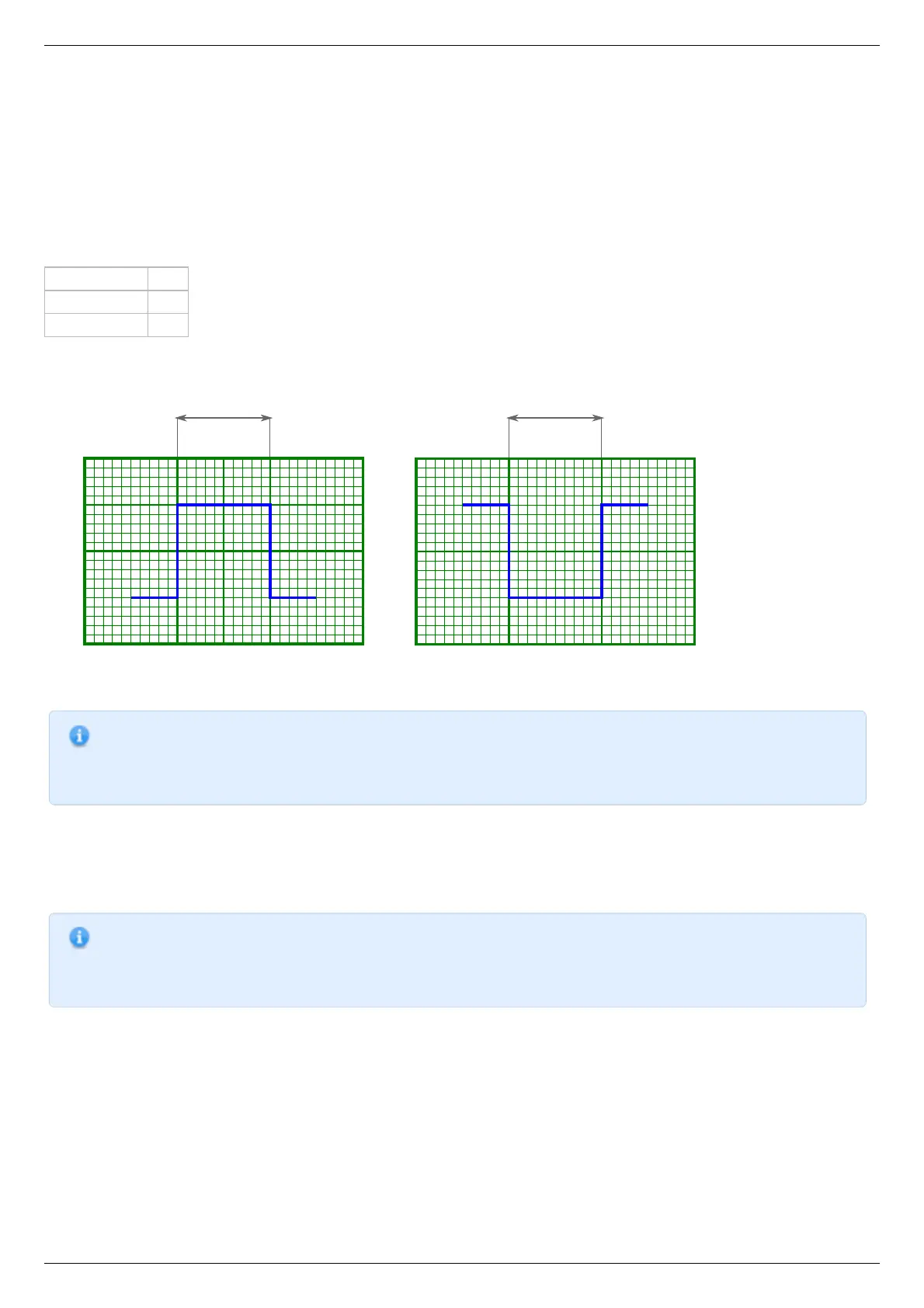
Inversion of input and output syncronization pulse illustrated
Note. If simultaneous start of several controllers in a multiaxis system is desirable, minimum input pulse length should
be the same for all controllers. Contact debouncing should not be used in systems with no mechanical contacts and
short noise pulses in synchronization input channel. One should use an RC-circuit which would filter these noise
pulses instead.
Synchronization in important in multiaxis systems because it allows one to start movement on several axes simultaneously. To do this
all axes are prepared to start the movement, all slave axes are set to start moving on input synchronization pulse, one master axis is
set to output a synchronization pulse on the start of the movement. Master axis output is connected to slave axes' input. In this setup
any movement of the master axis leads to immediate response of all connected axes.
Note. One should set minimum input sync pulse length to 0 if this kind of connection is used. This disables contact
debouncing, but since there are no mechanical contacts it is not needed. If minimum input sync pulse length is not
zero then to avoid desynchronization of master and slave axes one should set input sync pulse length the same for all
controllers, connect syncout to both master and slave inputs and issue start command by activating input manually.
Synchronization input and output are independent from each other and other means of motion control. Control through XiLab
application or any other user application, joystick control and left-right buttons control are independent of input/output synchronization
state. Last command always takes priority. For example, a movement command sent from XiLab will cancel current movement which
happened because of input sync pulse, but will not affect output sync state. Next input sync pulse will cancel current movement
initiated by user program and will replace it with movement command according to sync in settings.