Encoder connection
The encoder is connected to the controller via D-SUB 15 pin connector, which is in all systems ( controller board, one-axis and two-axis
in box
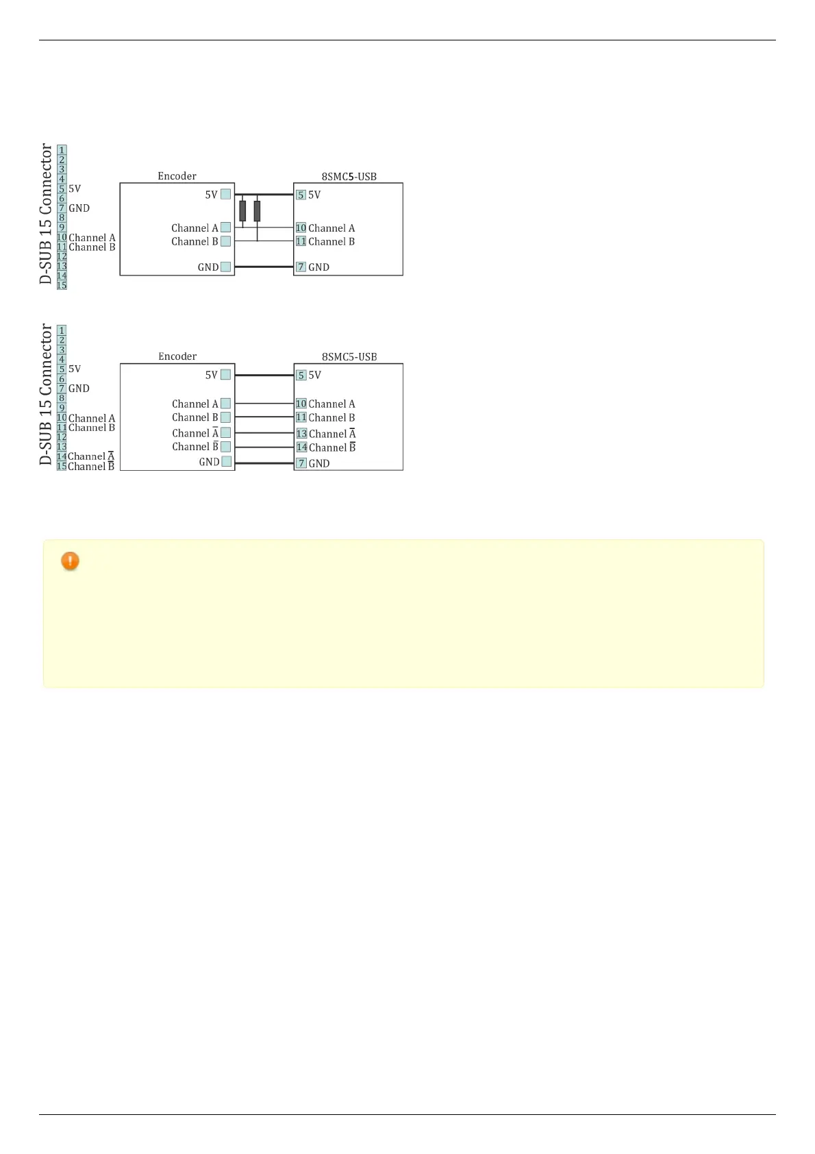
The diagram of single-ended encoder connection using D-SUB 15 pin connector.
The diagram of differential encoder connection using D-SUB 15 pin connector.
See also the Example of a motor connection chapter.
Warning. Encoder inputs of the controller internally pulled up to logic one by using the 5.1kΩ resistors. Frequently
encoder outputs are of "open collector" type equipped with internal pull-up resistor. During the data transmission they
provide good characteristics while passing from higher logic level to lower. However, the pass from logic 0 to logic 1 is
more graduate. It passes through the RC circuit formed by pull-up resistor and cable capacitance. This is the most
important thing if the cable is long. If the internal pull-up is not sufficient, the pull-up resistor with r=1.5kΩ may be
added for every +5V to each output in order to improve the transmission speed parameters; before doing that please
check if the open collector of the encoder can transmit 5mA current. The resistors insertion diagram is shown above.
The maximum operating speed for quadrature encoder may be increased by adding a push-pull driver with the
outgoing current over 10mA to its output, providing quick 0 - 1 and 1 - 0 transmission edges.