3.2. Example of a motor connection
General case
Positioner standard connection diagrams
Example
Preparation
Connecting the motor and encoder to the
controller
3.2. Example of a motor connection
General case
To connect a motor to the controller please refer to positioner connector, and
use the scheme of positioner connection:
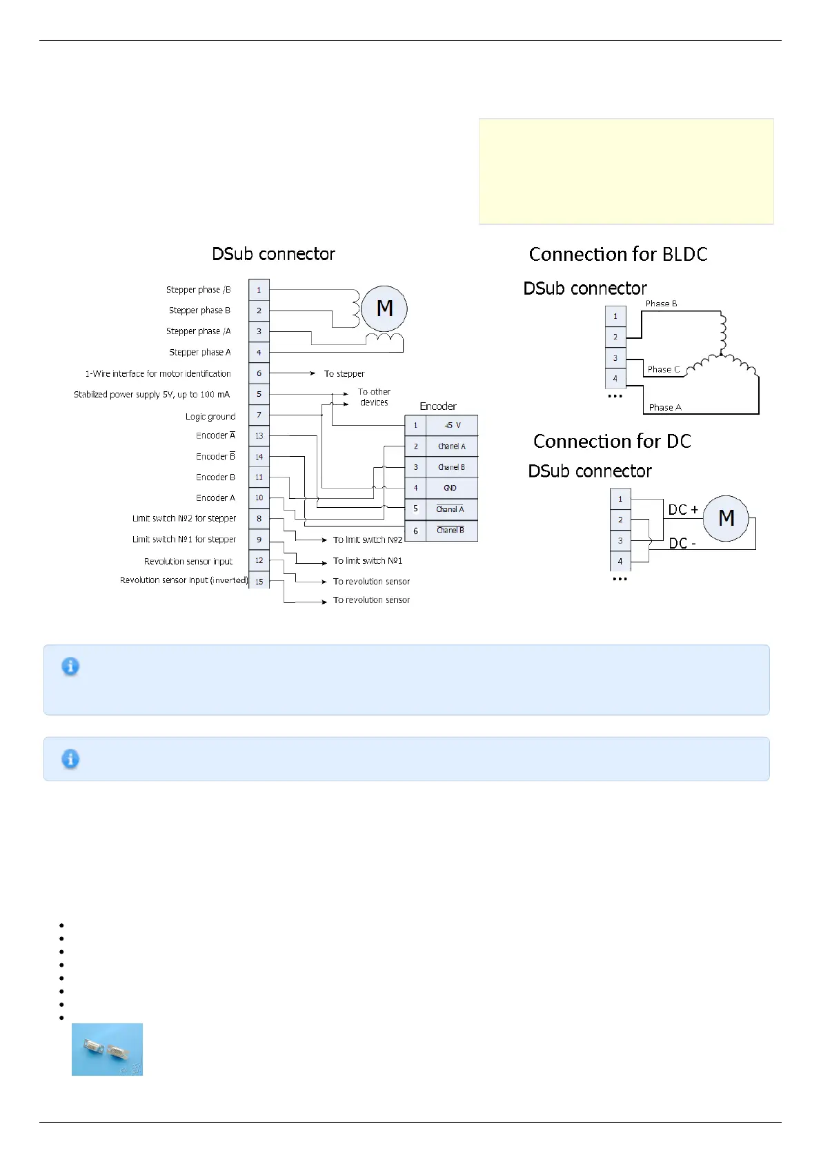
Positioner standard connection diagrams
General diagram of positioner and encoder connection using Dsub connector.
Note. If A and B encoder channels work in open drain mode, some extra pull-up of encoder outputs to 5V power
voltage using the resistors may be required at high rotation speeds in order to provide the maximum signal
transmission speed (see Operation with encoders ).
Note. Only firmwares 4.1.0 and older support BLDC.
Example
Consider the connection of the two-phase stepper motor Nanotec ST5918L3008-B with encoder CUI INC AMT112S-V to controller
8SMC5-USB.
Preparation
To get started, we need:
Motor;
Encoder;
Pinout of D-SUB connector for 8SMC5-USB;
Motor datasheet ;
Encoder datasheet ;
Soldering equipment: soldering-iron, wires, flux, solder, nippers, heat shrink tubes of different sizes;
Screws M2.5x6 for fixing the encoder;
D-SUB cover + connector (male) and wires for cable manufacturing;