Connecting the motor and encoder to the controller
Before you begin, assemble the encoder in accordance with the appropriate instructions.
The motor without encoder. Note 2 holes M2.5 to which is usually attached an encoder
Motor with attached encoder
Let us look in the specification of the engine and find the wiring diagram (for Nanotec ST5918L3008-B it is at the bottom right in
the specification):
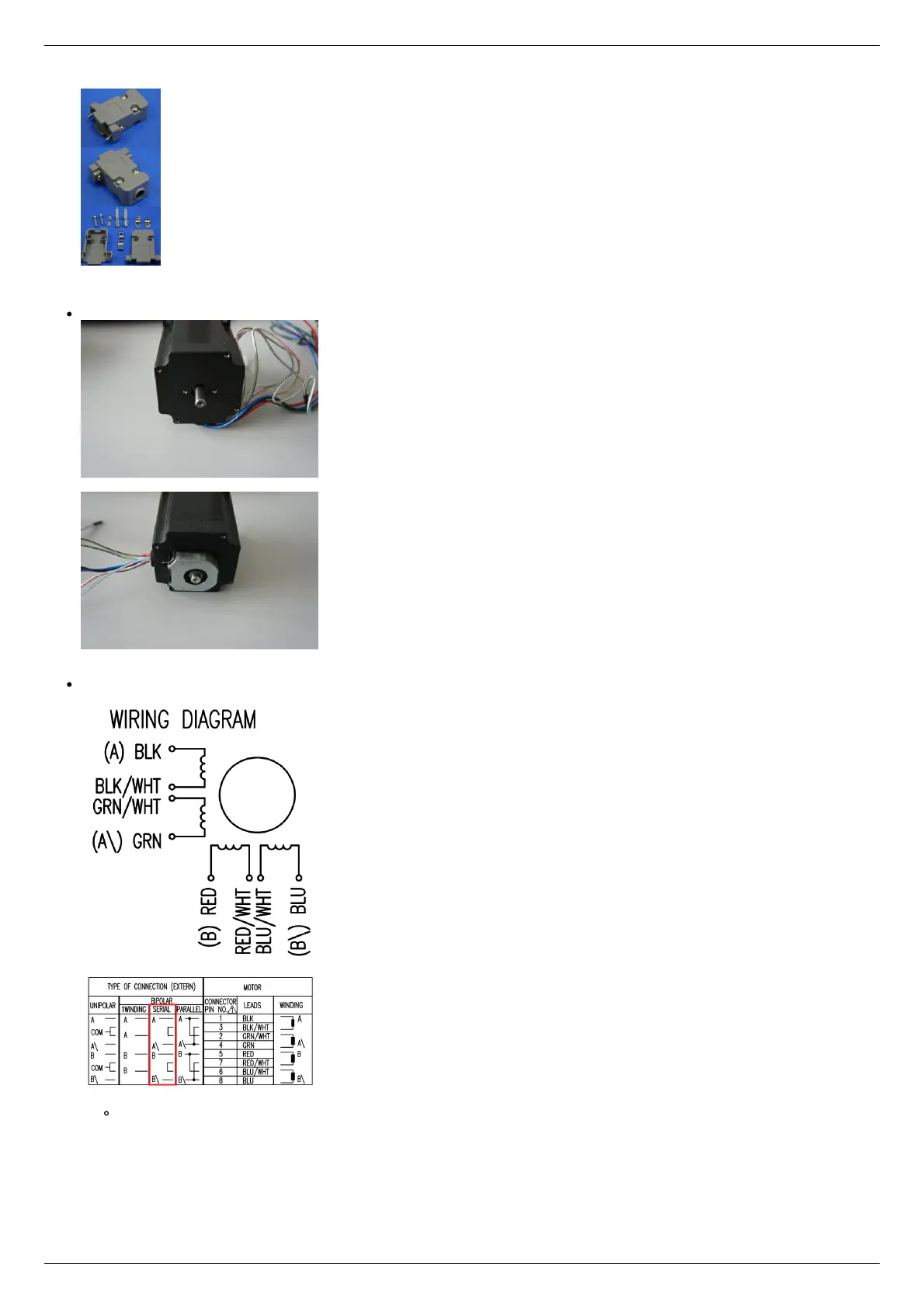
Motor contacts
Connection type
There exist serial and parallel winding connection and each type allows to obtain various characteristics for the motor. We
will connect the windings in series (red frame on the picture). To do this, wires having two colors BLK/WHT and GRN/WHT,
as well as RED/WHT and BLU/WHT must be connected to each other in pairs. Next, you need to put in accordance A, not A,
B, not B pins of controller to contacts of motor windings ST5918L3008-B: black, green, red, blue. One winding is a
connection of A and not A or B and not B. After the connection between a two-color wire, you will get that one winding of
the motor is black - green connection, other is red - blue. Therefore, matching contacts will be the follows: black - A, green
- not A, red - B, blue - not B. It can be seen in the picture above Connection type.