To connect encoder, open its datasheet and find 5 contacts on encoder connector: A+ (channel A), B+ (channel B, shifted
relative to A by 90 degrees), Z+ (rev counter), 5V, GND. They should be taken from the encoder as 5 separate wires and
put together with the wires from the motor as they then go to a connector. CUI INC AMT112S-V encoder has 18 pin input,
therefore it is needed to make a cable with the same connector on the end to output necessary signals:
Encoder contacts A+, B+, Z+, 5V and GND corresponds to 10, 11, 12, 5, 7 pins of D-SUB male connector respectively.
For convenience, use the next tables (the number in parentheses indicates pin on the corresponding connector):
Encoder pin D-SUB pin
A+ (10) Encoder A(10)
B+ (8) Encoder B(11)
Z+ (12) Revolution sensor input (12)
5V (6) Output 5V, 100 mA (5)
GND (4) Logical ground (7)
Motor pin D-SUB pin
A (BLK) phase А (4)
not A (GRN) phase not А (3)
B (RED) phase B (2)
not B (BLU) phase not B (1)
Solder the above contacts to D-SUB male connector:
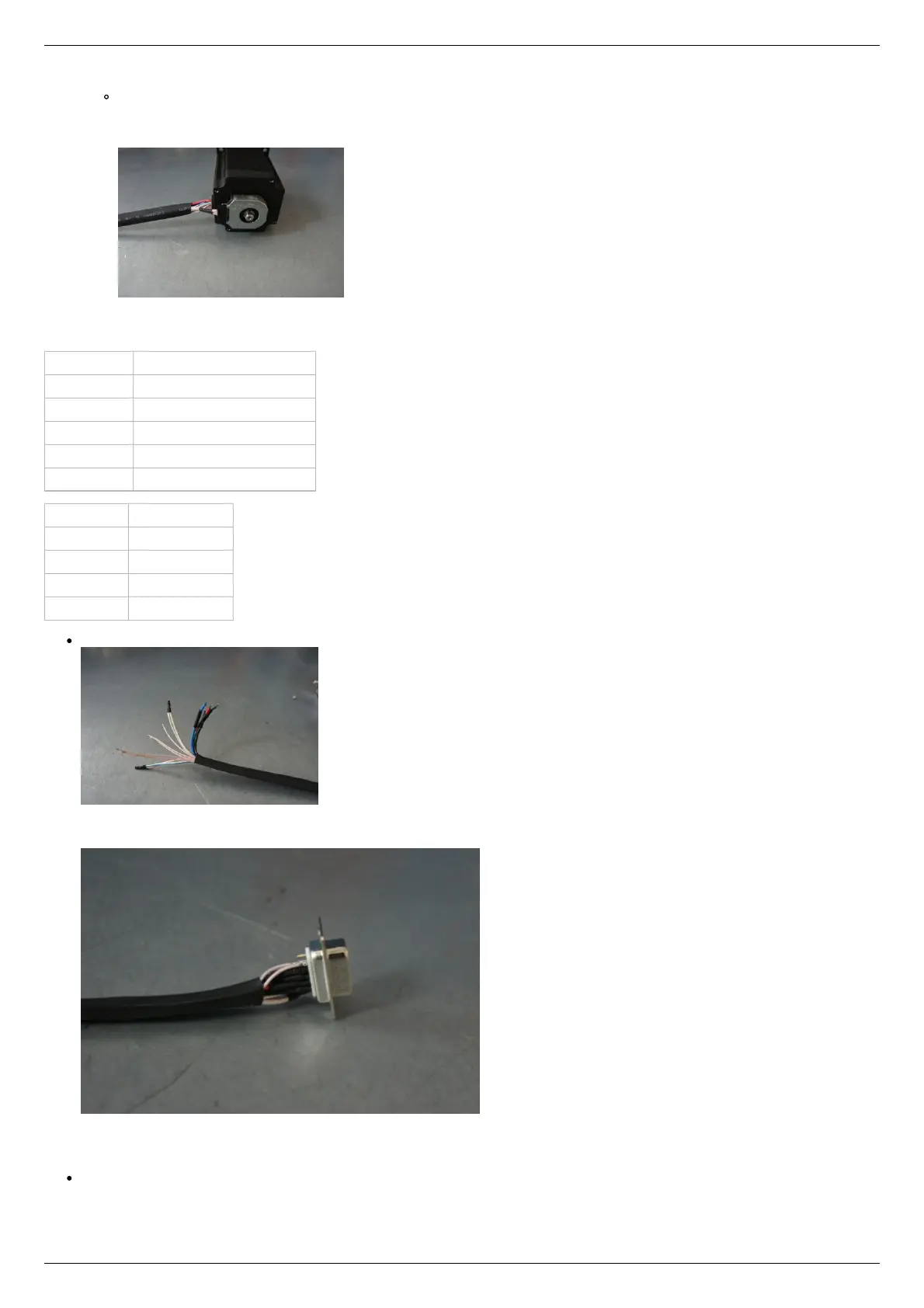
The wires from the motor and encoder in a heat shrink tube. Note the presence of small heat-shrinkable tubes for wires going to
the motor windings (BLK, GRN, RED and BLU), as well as two-colored wires joined together (BLK/WHT and GRN/WHT, RED/WHT
and BLU/WHT). The thin wires are an encoder contacts (5 pcs).
Ready cable from the motor with the D-SUB connector on its end
Recommendation: use heat shrink tubes of a small diameter (2-3 mm) while soldering contacts to D-SUB connector, and large
diameter to skip through them all the wires coming from the motor and encoder. Put them before soldering.
Put D-SUB connector into the cover.