4.3.3. Limit switches
Limit switches designation
Limit switches are designed in order either to prevent the stage movement out of permissible physical movement range or to limit its
movement range according to user-defined requirements. Incorrect setting of the limit switches may result to stage jam if the
controller goes beyond the permissible range.
General settings
If the limit switch is active, a corresponding flag is placed in the state structure and the appropriate icon (left or right) is displayed in
XILab Main window. The controller can either stop any movement in the direction of any active limit switch (left or right) or stop the
movement to the single limit witch (left or right) or not to limit the movement. Limit switches settings are performed in XILab software
(see the Motion range and limit switches section).
Programmable motion range limitation
If there are no hardware limit switches for the motion range but the stage requires such limitation, the programmable limiters can be
used. For doing that, the limiters should be switched to limitation mode according to position reading (see the Motion range and limit
switches section). The left and right margin fields are used (the right margin value should be higher than the left one). In this mode,
the left limit switch is active if the actual position is less than the left margin value and the right one is active if the actual position is
greater than the right margin value. The operation time is about one millisecond.
Warning. The programmable motion range limitation is reliable only if there is no direct setting of the new position
by ZERO or SPOS commands, or if there is no steps loss or encoder malfunction if it is used for positioning, or if there
is no frequent power-cut during the rotation. If any of these problems appears, the programmable range should be re-
adjusted. The appropriate reference sensor allows the automatic re-adjustment using the automatic Home position
calibration feature.
Hardware limit switches
The controller may operate with limit switches based either on dry contacts, or on optocouplers, or on reed switches, or on any other
sensor types generating a 5V TTL-standard "logic one" electric signal in one state and a "logic zero" in the other. Each limit witch may
be configured independently. There is also possible to change the position of limit switches or their polarity in software.
Note. Limit switches are also useful for automatic Zero position calibration .
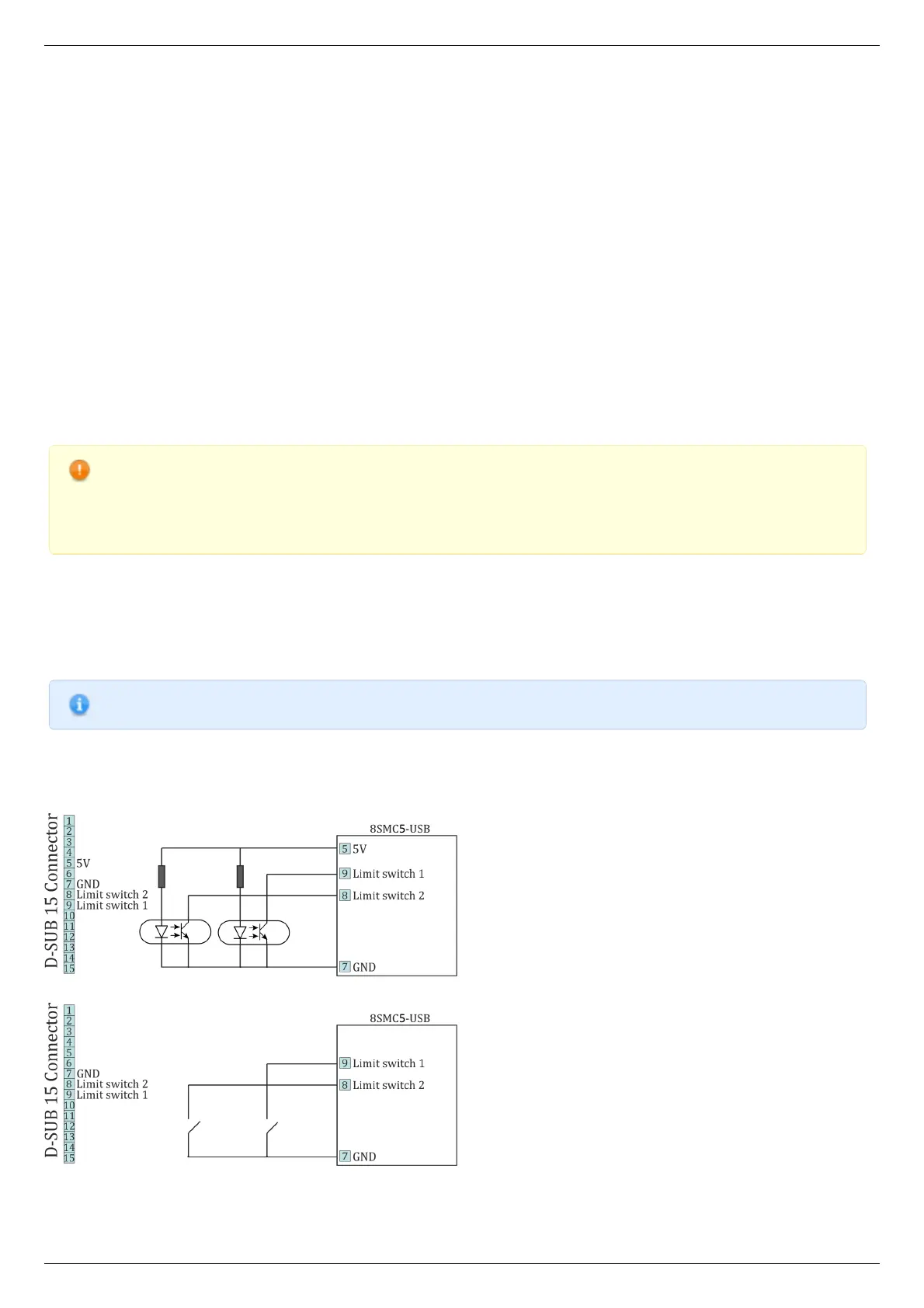
Limit switches connecting instructions
Limit switches should be connected to D-SUB connector pins as it is shown at the diagrams:
The "optocoupler" limit switches connection diagram.
The "dry contact" limit switches connection diagram.
Limit switches location on translators