4.1.1. Controller board 8SMC5
Dimensions and arrangement
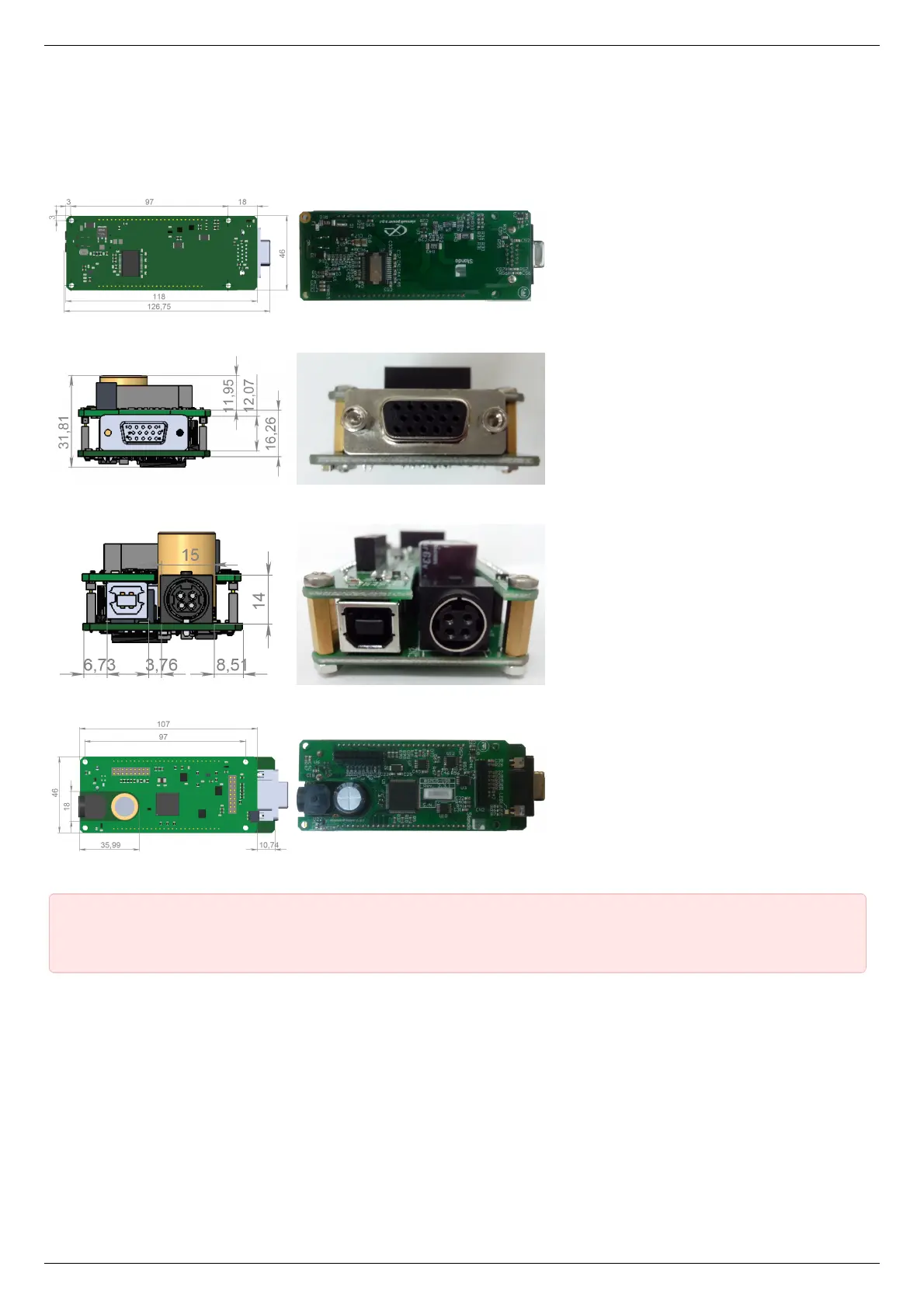
Structurally the controlled is designed as two boards, 46x126,75mm each, rigidly connected to each other. A logic controller and
control systems are mounted at the bottom board, a power part is at the top board. A radiator at the power part is available.
Top view on the controller. The view from power part and radiator side.
Front view on the controller. The view from stage cable side.
Rear view on the controller. The view from DIN and USB-b connectors side.
Bottom view on the controller. The view from backplane connectors side.
IMPORTANT. If you are mounting the radiator to the power part by yourself, please make sure that there is no
contact between heat-conducting surfaces and conductive elements of the unit. Such contact may damage the power
circuit! This warning is applicable only to controllers supplied without body.
Connectors
Positioner connector
A female DSub 15-pin connector for positioner is mounted on the controller board.