TUP500 Series Product Specifications 4-4
4.2. Operating Unit Specifications
4.2.1. Switch
POWER Switch Turns the printer’s power ON and
OFF.
SW1 Feeds and discharges paper
SW2 Clears errors
Notes:
1. Be aware that the operation of the main unit may vary according to its conditions.
4.2.2. LED
LED1 POWER Green
LED2 ERROR Red
Notes:
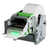
See Figs. 4.1.2.A. and 4.1.2.b> for the positions of the switches and LED.
4.3. Interfaces
No interface card is included with this printer.
See section 2.2 for details on the optional interface card to use.
4.4. DIP Switches
Changeable on the top of the main unit.
Notes:
1. The direction for accessing the DIP switches will vary according to the layout of the con-
trol board (card chassis).
2. It is necessary to remove the card chassis (U) to access the DIP switches.
3. See secton 12.1 for the DIP switch positions.
 Loading...
