57
EN
• Make all the desired tweaks in the plugin („6.5.1 Explanation of the Autoleveler CA-Plugin“).
- Number of scanning points in X- and Y-direction
- Tool Z Offset
- Manual or Auto Zero
- Settings
• Click Create GCode and send to UCCNC. It
may take some time to load the program into
UCCNC. In particular, a high number of probe
points increases the loading time.
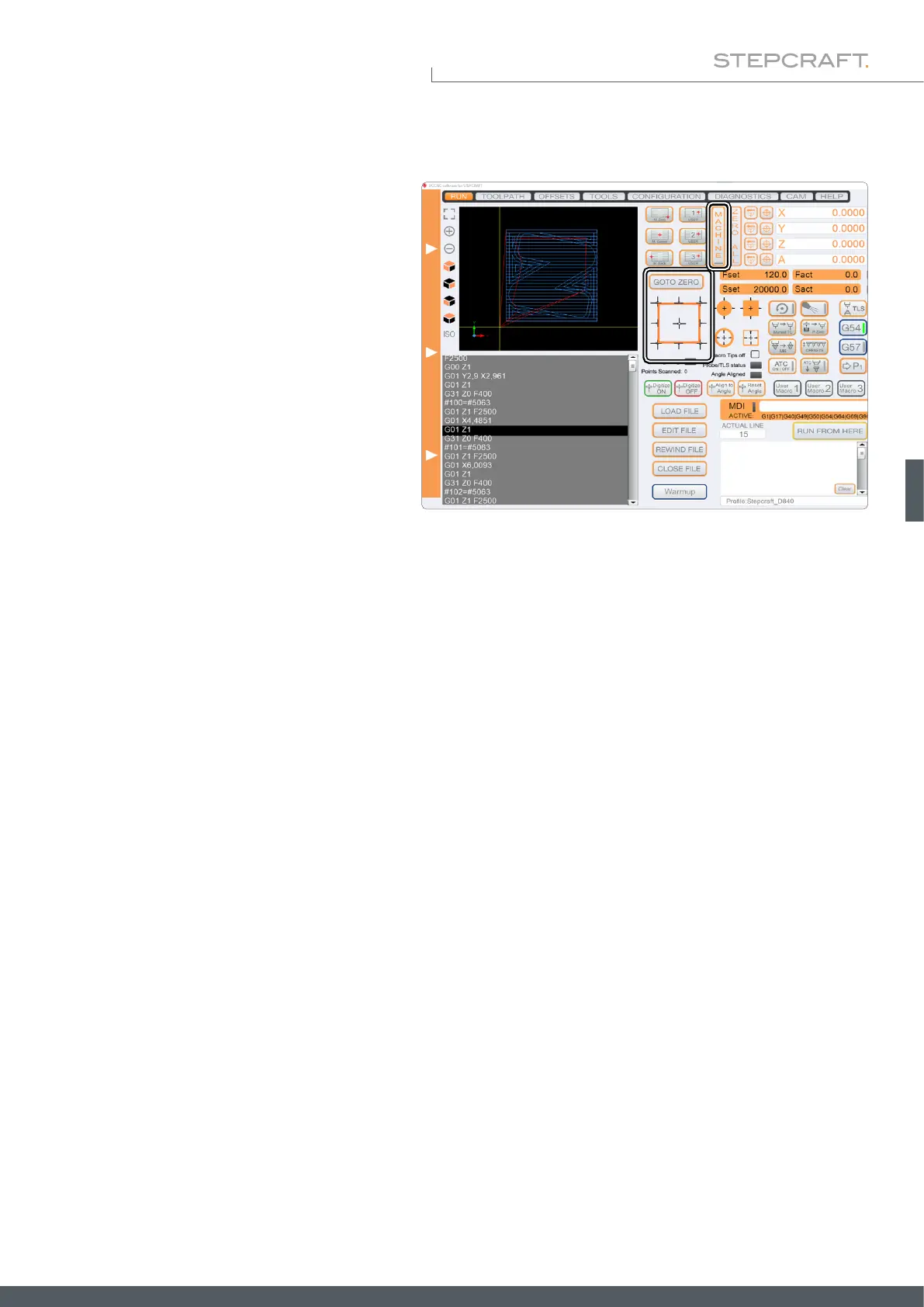
• Use the contour probing macros to nd the X-,
Y- and Z-zero points, and then click Goto Zero.
• Start the milling program with Cycle Start. The surface is now scanned. After this process has been completed, the
milling program pauses. Take note of the current machine coordinates.
• Use this pause in the milling program to insert your tool. Manual control of UCCNC is still possible. Use the manual
control to set the Z-zero point with the tool. Move back to the starting position where the program was paused.
• Continue the process by clicking Cycle Start.
6.5.3 Scanning a Surface ("Create")
This application uses the 3D probe to scan a 3-dimensional surface. A multitude of measurements results in a three-di-
mensional point cloud, in which each point stands for a coordinate. From this cloud an object can be created for further
use. To utilize this function you need the following software:
• UCCNC-Plugin Autoleveler CA.
• A CAD / CAM software like Vectric VCarve or AutoDesk Fusion 360.
• A software like MeshLab to process the point cloud.
To scan an object, follow these steps:
Prepare your workpiece by xing it with a method of your choice. It is especially recommended for this application to use
a vise (such as item 12378 centering vise CV-140), double-sided tape (item 12482 adhesive sheet) or a vacuum table.
The advantage of these methods, is that the workpiece surface remains free. The next two chapters describe this process
once using VCarve and Fusion 360.