00732467 Rev. D Page 85 of 110
13.2.1 Device Inspection Procedure
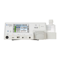
Reference section 7.1 gi4000 Electrosurgical Unit for system features and diagrams.
Front Panel Inspection
1. Inspect the front panel and touchscreen for major scratches, indentations, cracks, dust
and debris.
2. Ensure that all indicator icons and symbols on the unit are present and visible.
3. Inspect the output receptacles (PSS Return, ArConnect®, Monopolar and Bipolar) for
any damage, dust and debris. Clean with air if necessary.
4. Check power ON/OFF switch for wear by pressing it ON and OFF with the power cord
disconnected.
5. Inspect lavage pump head and pump head lid for any signs of damage or excessive
wear.
6. Inspect functionality of front panel indicator lights: all illuminate and cycle upon startup.
Rear Panel Inspection
1. Inspect the gi4000 rear panel for any missing screws.
2. Inspect the footswitch receptacle for any damage.
3. Inspect the equipotential (ground) terminal for looseness or signs of damage.
4. Inspect the AC mains connector and fuse box for looseness, signs of damage.
5. Inspect fuses for damage.
6. Inspect the vent ports for any dust or debris. Clean by wiping with cloth or spray with
air/vacuum, if necessary.
7. Inspect the speaker ports for any dust or debris. Clean by wiping with cloth or spray with
air/vacuum, if necessary.
Bottom Panel Inspection
1. Inspect the bottom panel of the gi4000 for major scratches, indentations, cracks, dust
and debris.
2. Ensure that all four (x4) non-slip rubber feet are present and secured to the bottom of
the unit.
3. Inspect the vent ports for any dust or debris. Clean by wiping with cloth or spray with
air/vacuum, if necessary.
Footswitch Inspection
1. Inspect the footswitch cable and connector for any signs of damage, including to the
pins and connector housing.
2. Inspect the footswitch housing for signs of damage including cracks, dents, dust and
debris. See section 10.3.2 Care, Cleaning and Storage for detailed cleaning
instructions for the footswitch.
3. Test the pedal action for both irrigation and power pedals by depressing each pedal with
your foot several times.
4. Test the footswitch connector in the back of the gi4000, ensuring proper mating
between the connector and the receptacle.