K
Kevin NelsonJul 27, 2025
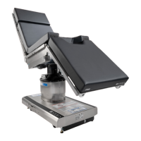
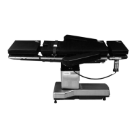
What to do if Steris 4085 table does not raise/lower using hand control?
- SscottgarciaJul 27, 2025
If the Steris Medical Equipment table is not raising or lowering with the hand control, it could be because the hand control is not active. Try pressing any button on the hand control (except the STOP button). If that doesn't work, the hand control might be faulty and need to be replaced.