7-16
764333-766
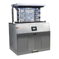
Figure 7-41. Leg Switch Replacement
7.26 LEG SUPPORT LOCKING DEVICE
REPLACEMENT
Replace leg support locking device as follows:
1. Position tabletop to level.
2. Turn Main Power Switch to OFF and remove
battery fuse (refer to supplied Operator Manual for
more information).
3. Remove leg section and set safely aside.
4. Remove both left and right leg switch plate cover
(see Figure 7-40).
5. Remove closing plate.
6. Remove spring and lock (see Figure 7-42).
7. Verify locking device functions properly.
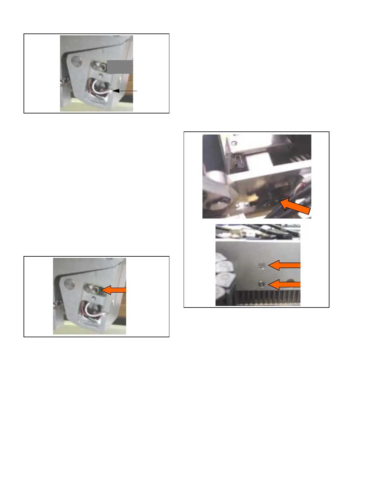
Figure 7-42. Leg Support Locking Device
Replacement
7.27 KIDNEY SWITCH REPLACEMENT
Replace kidney switch as follows:
1. Position tabletop to level, slide to maximum head
end.
2. Raise kidney section to maximum.
3. Turn Main Power Switch to OFF and remove
battery fuse (refer to supplied Operator Manual for
more information).
4. Remove tabletop seat section per S
ECTION 7.20.1,
S
EAT SECTION.
5. Remove seat plastic cover.
6. Remove seat section accessory rail assembly by
removing and saving three screws and spacers.
7. Remove top cover.
8. Remove wire protection cover.
9. Disconnect switch from main CPU board (P77
connector).
10. Remove both screws fastening switch to frame
and replace switch (see Figure 7-43).
11. Reassemble in reverse order. Adjust as needed for
proper operation.
12. Verify switch status on hand control.
Figure 7-43. Kidney Switch Replacement
7.28 TRENDELENBURG SENSOR
REPLACEMENT
Replace Trendelenburg sensor as follows:
1. Position tabletop to level, slide to maximum head
end.
2. Turn Main Power Switch to OFF and remove
battery fuse (refer to supplied Operator Manual for
more information).
3. Remove tabletop seat section per S
ECTION 7.20.1,
S
EAT SECTION.
4. Remove seat plastic cover as follows:
a. Remove four top and four side screws from
both head-side and foot-side seat cover
(see Figure 7-33).
b. Slide plastic covers to remove from table.
Switch
Switch
Mounting
Screws