7-7
764333-766
7.10 CASTER REPLACEMENT
Replace a faulty caster as follows:
1. Engage floor locks.
2. Remove table column cover per S
ECTION 7.3, TABLE
COLUMN COVER ASSEMBLY.
3. Remove appropriate base cover per S
ECTION 7.4,
T
ABLE BASE COVER ASSEMBLY.
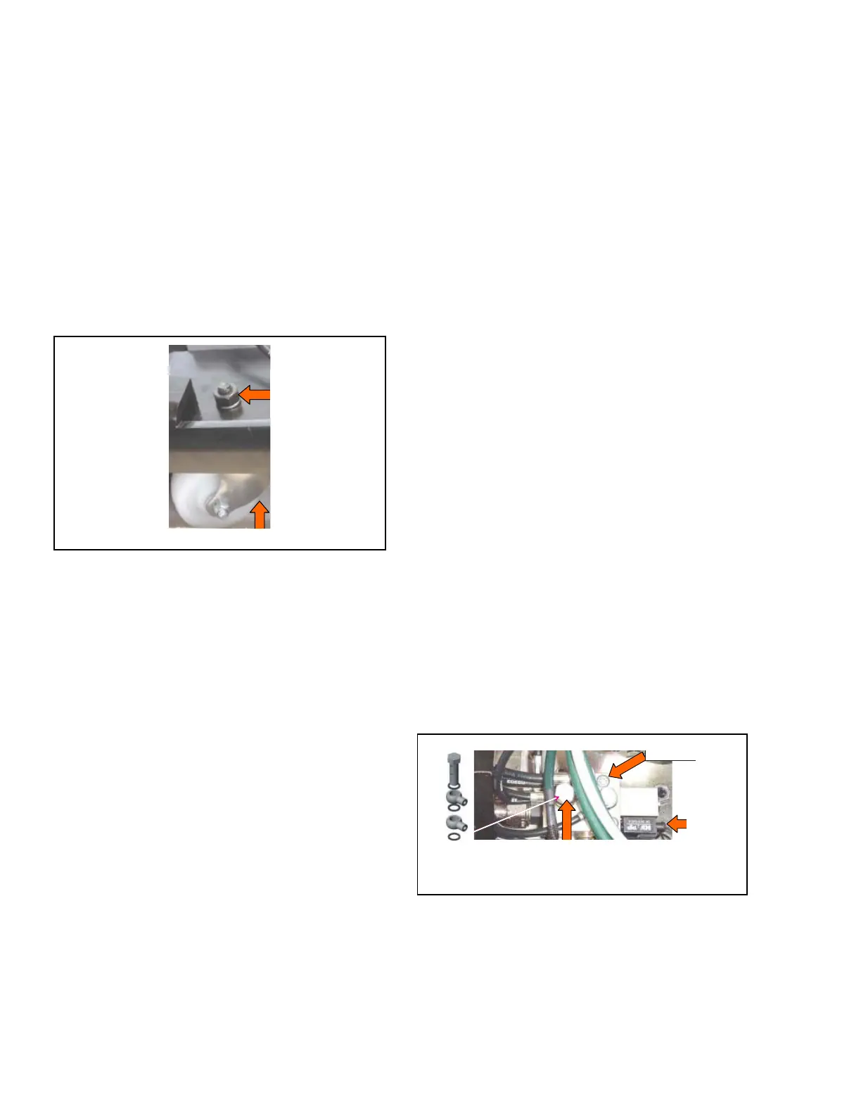
4. Remove flat washer, lockwasher and nut fastening
caster to table base (see Figure 7-17).
5. Replace faulty caster and reassemble in reverse
order.
6. Torque nut to 20 N•m (177 lbf•in).
Figure 7-17. Replace Caster Assembly
7. Move table to a known level floor. Ensure table does
not rock when on casters. If rocking is discovered,
proceed as follows:
a. Identify casters not contacting floor. Mark one for
shim placement.
b. Remove table column cover per S
ECTION 7.3,
T
ABLE COLUMN COVER ASSEMBLY.
c. Remove appropriate base cover per S
ECTION 7.4,
T
ABLE BASE COVER ASSEMBLY.
d. Stack shims (P150832-657) under indicated caster
wheel until fit is tight. Note quantity used.
e. Carefully tilt and secure table enough to allow
removal of caster and to return caster with needed
shims.
f. Remove flat washer, lockwasher and nut
fastening caster to table base (see Figure 7-17).
g. Position shims (determined in Step 7d) between
caster and table base.
h. Reassemble in reverse order. Torque nut to
20 N•m (177 lbf•in).
7.11 FLOOR LOCK MANIFOLD
ASSEMBLY REPLACEMENT
Replace a faulty floor lock manifold assembly as
follows:
1. Release floor locks. Ensure table is on casters and
not floor locks.
2. Turn Main Power Switch to OFF and remove
battery fuse (refer to supplied Operator Manual for
more information).
3. Remove table column cover per S
ECTION 7.3, TABLE
COLUMN COVER ASSEMBLY.
4. Remove appropriate base cover per S
ECTION 7.4,
T
ABLE BASE COVER ASSEMBLY.
5. Carefully lift battery #2 from table base and place
on top of battery #1.
6. Remove all hydraulic and electrical connections
from manifold assembly. Note and record various
connections for ease of reassembly. Discard all
hydraulic screws and sealing washers.
NOTE: Refer to 4085 Surgical Table Hydraulics figure
in the Illustrated Parts Breakdown section for hose
identifications.
7. Remove both stainless-steel socket head cap screws
fastening floor lock manifold to manifold spacer
(see Figure 7-18).
8. Replace manifold assembly.
9. Clean manifold area and reassemble in reverse
order. Replace sealing washers and torque
hydraulic screws to 12 N•m (106 lbf•in).
NOTE: Replace (do not reuse) hydraulic screws and
sealing washers (see Figure 7-18). Ensure bolt threads,
manifold threads and hose connectors are free of rubber
seal particles.
Figure 7-18. Replace Floor Lock Manifold
7.12 HYDRAULIC PUMP REPLACEMENT
Replace a faulty hydraulic pump as follows:
1. Position tabletop to level, slide at zero.
2. Raise tabletop to full height.
Washer,
Lockwasher
and Lock Nut
Caster Assembly
Hydraulic Screw
Mounting Screw
Two-Way Hydraulic
Screw and Sealing
Washers
Electrical
Connection