7-20
764333-766
2. Turn Main Power Switch to OFF and remove
battery fuse (refer to supplied Operator Manual for
more information).
3. Remove tabletop seat section per S
ECTION 7.20.1,
S
EAT SECTION.
4. Remove tabletop kidney section per S
ECTION 7.20.2,
K
IDNEY SECTION.
5. Remove seat section accessory rail assembly by
removing and saving three screws and spacers.
6. Remove side cover.
7. Remove seat plastic cover as follows:
a. Remove four top and four side screws from
both head-side and foot-side seat cover
(see Figure 7-33).
b. Slide plastic covers to remove from table.
8. Remove six lower screws from table column plastic
cap (see Figure 7-21) and allow table column cover
to lower to base cover.
9. Remove seat section wire protection cover.
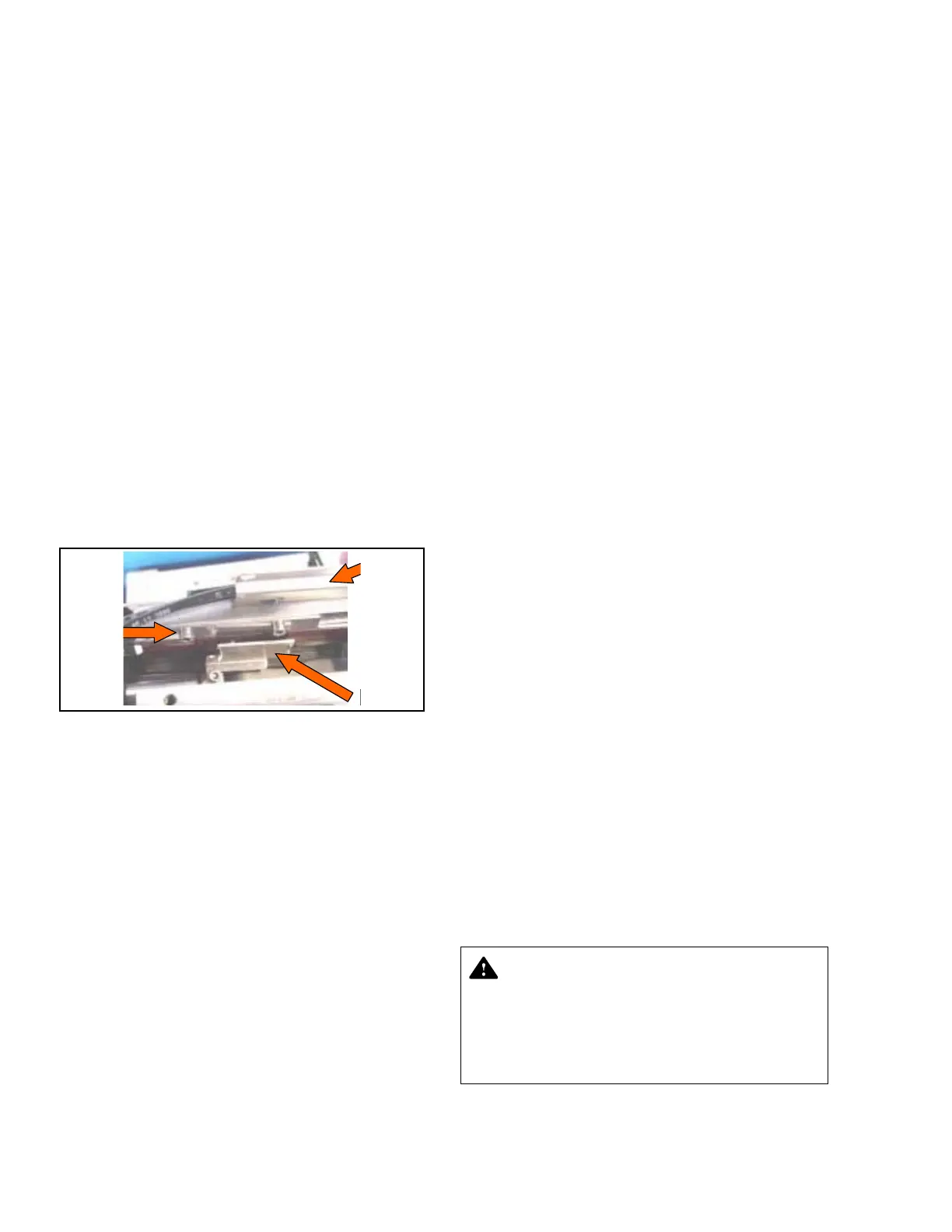
10. Remove right-side wire and hose protection cap
(only right side). See Figure 7-55.
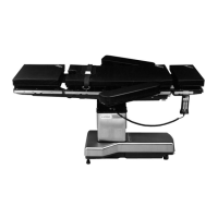
Figure 7-55. Remove Back Sensor
11. Remove wiper from cylinder rod end (only right
side).
12. Disconnect sensor from CPU motherboard (P74
connector) and remove sensor.
13. Reassemble in reverse order and adjust tabletop
to level.
14. Verify cursor full movement is centered as much
as possible on sensing strip (does not approach
edges too closely).
7.35 HYDRAULIC FLUID
CONTAMINATION
This procedure is for use when hydraulic fluid
contamination is suspected inside the pump or one of
the manifolds.
1. Remove table column cover per S
ECTION 7.3, TABLE
COLUMN COVER ASSEMBLY.
2. Remove appropriate base cover per S
ECTION 7.4,
T
ABLE BASE COVER ASSEMBLY.
3. Unlock table and lower tabletop to lowest position.
4. Using a suction bottle and facility vacuum system,
remove all hydraulic oil from reservoir.
NOTE: Failure to use a suction bottle results in oil
contamination of facility vacuum system.
5. Refill reservoir to approximately 3/4 full or about
1" (25.4 mm) from top.
6. Fully articulate all table sections except slide five to
six times. Ensure floor locks and kidney elevator are
included.
7. Repeat Steps 3 through 6 two more times.
8. Clean entire area outside all hose fittings to ensure
no additional dust or lint are introduced into
hydraulic system when disasssembled.
9. Replace manifold(s) (per S
ECTION 7.19, MAIN
VALVE BLOCK REPLACEMENT) and/or pump and
motor assembly.
10. Remove block and tie-down.
11. Repeat Steps 3 through 6 six more times.
12. Let table sit idle for 20 minutes to allow all
entrained air in oil to rise.
13. Repeat Step 6 ten more times to ensure air removal
and inspect for leaks.
14. Disconnect, one at a time, hydraulic lines to floor
locks and purge each line. Remove as much oil as
possible from foot cylinder and refill manually
before reconnecting hydraulic line.
15. Level tabletop and raise table to half height.
Measure distance from tabletop to floor. Note this
dimension.
16. Allow sufficient time (minimum 30 minutes) to
ensure no downward drift. Measure distance
from tabletop to floor and compare to distance
recorded in Step 15.
17. Reassemble table and return to service.
7.36 LINEAR RAIL BEARING
REPLACEMENT
NOTE: Full tabletop weight is present on these cartridge
bearings. The bearing assembly attaches the sliding tabletop
Hose
And Wire
Protection
Cap
Back
Sensor
Wiper
CAUTION – POSSIBLE EQUIPMENT
DAMAGE: Use care when separating the
bearing assembly from each side of the table
as the sliding tabletop side member is now
free-floating when the bearing assembly is
removed. Avoid bumping or misaligning the
slide potentiometer pulley.