3-2
150832-639 Operator Manual Installation Instaructions
NOTE: Where the integrity of the external protective earth conductor
arrangement is in doubt, use battery power only.
6. Turn Main Power Switch to ON. Switch turns Green and plug symbol
on INTELLIPOWER
®
LED Display lights.
NOTE: A green Main Power Switch indicates facility power is available
to the STERIS 4085 General Surgical Table. A lighted plug symbol on
the LED Display indicates the batteries are charging. Refer to S
ECTION
5.5, BATTERY CHARGING PROCEDURE.
7. Route power cord to eliminate Tripping Hazard for facility
personnel.
8. Remove hand control from package and plug into appropriate
socket on table column (see Figure 3-3 and Figure 3-4) as follows:
a. Lift appropriate protective cover on connection panel.
b. Align red mark (or arrow) on hand control plug with red mark
on table socket.
c. Push hand control plug into table socket until a "click" is
heard.
d. Place hand control on table side rail.
9. Remove foot control (optional) from package and plug into
appropriate socket on table column (see Figure 3-4 and
Figure 3-5) as follows:
NOTE: The optional foot control allows operator to control HEIGHT,
TREND and TILT movements.
a. Lift appropriate protective cover on connection panel.
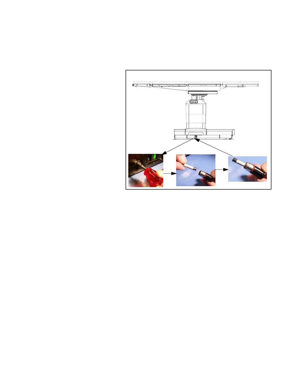
Figure 3-1. Install/Remove Battery Fuse
C-MAX 05
Ensurecapscover
socketswhennotin use.
SERVE