7-9
764333-766
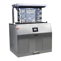
Figure 7-21. Table Column Plastic Cap
10. Remove plastic column cover cap.
11. Reinstall cover by reversing procedure.
NOTE: On plastic column cover cap reinstallation,
ensure distance between tilt cylinder shaft and nut is 1-
1/8" (29 mm) when reconnecting tilt cylinder (as shown
in Figure 7-22).
12. Restore RTV seal (see S
ECTION 7.5.1, TWO-PART
BASE COVER (STAINLESS STEEL) or SECTION 7.5.2,
O
NE-PART BASE COVER (PLASTIC) of this
document).
Figure 7-22. Reconnect Tilt Cylinder Shaft
7.15 HEIGHT SENSOR REPLACEMENT
Replace the surgical table height sensor as follows:
1. Raise table to maximum height.
2. Turn Main Power Switch to OFF and remove
battery fuse (refer to supplied Operator Manual for
more information).
3. Remove table column cover per S
ECTION 7.3, TABLE
COLUMN COVER ASSEMBLY.
4. While holding height sensor cable, unscrew sensor
cable from base.
5. Slowly allow sensor cable to retract.
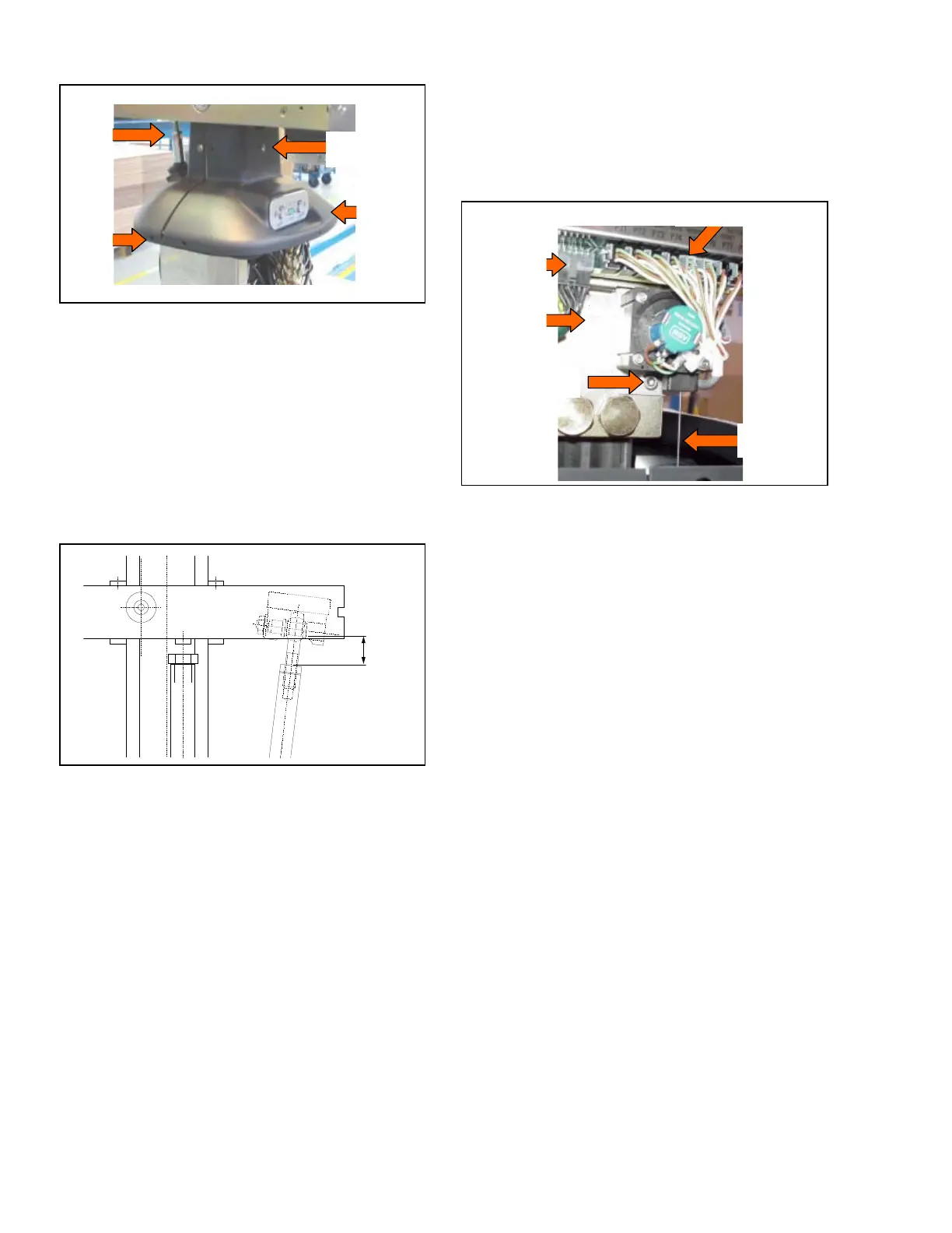
6. Remove CPU cover lower screw to gain access to
connectors (see Figure 7-23).
7. Disconnect P6 and P75 (height sensor) connectors
from CPU Board.
8.Remove both socket head cap screws fastening
height sensor to table base.
9. Replace sensor and cable by reversing procedure.
Figure 7-23. Height Sensor Replacement
7.16 TABLE CONTROL (CPU) BOARD
REPLACEMENT
Replace the table control (CPU) board as follows:
1. Raise table to maximum height.
2. Turn Main Power Switch to OFF and remove
battery fuse (refer to supplied Operator Manual for
more information).
3. Remove table column cover per S
ECTION 7.3, TABLE
COLUMN COVER ASSEMBLY.
4. Remove CPU Board cover and set aside.
5. Disconnect all lower connections from board (see
Figure 7-24).
6. Slide board down to gain access to upper
connections under plastic column cover cap.
7. Disconnect upper connections from CPU board and
remove board from table.
8. Replace board and reconnect table connections.
9. Test table for proper operation before returning
covers.
10. Reassemble in reverse order.
NOTE: Newer versions of control may require Dip
Switch setting.
Lower
Fastening
Screws
Tilt
Cylinder
Rod
Connection
Panel
Upper Fastening
Screws
P75 Connector
Sensor
Cable
CPU
Lower
Screw
P6 Connector
Sensor Screw