3-3
Installation Instaructions Operator Manual 150832-639
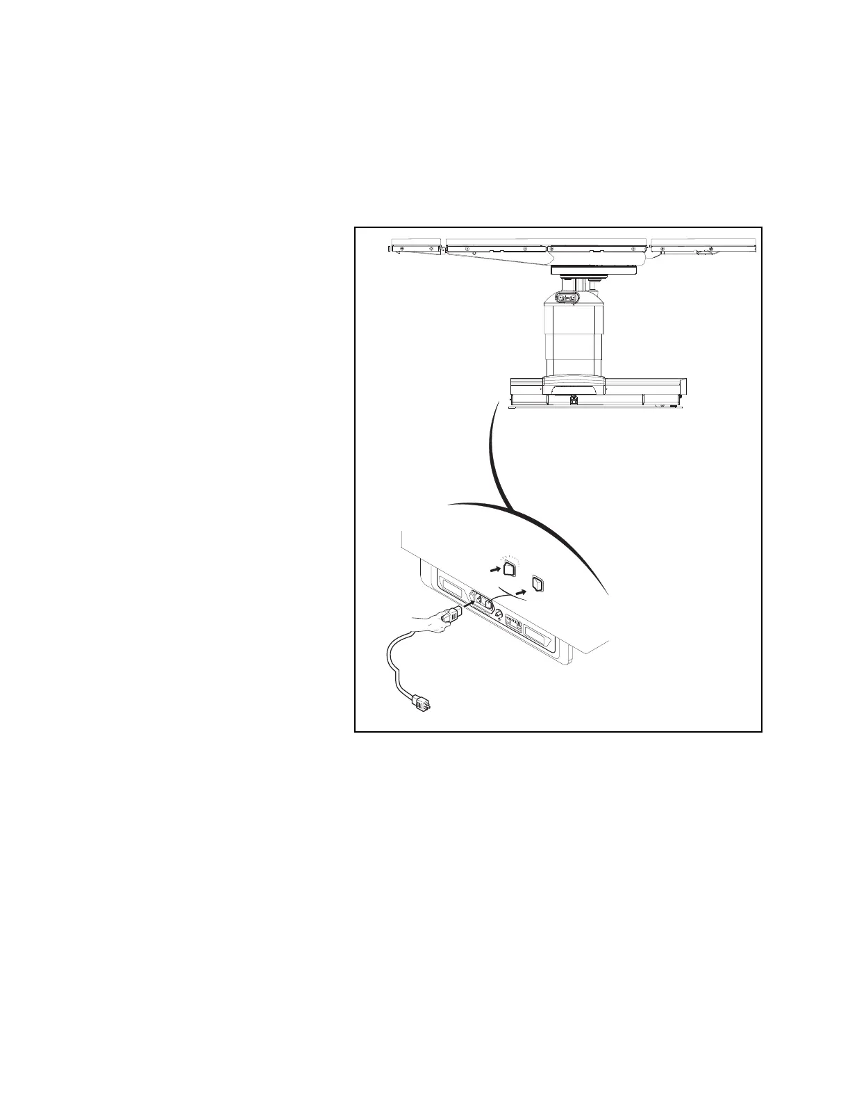
b. Align red mark (or arrow) on foot control plug with red mark on
table socket.
c. Push foot control plug into table socket until a "click" is heard.
d. Place foot control where it cannot be damaged.
10. Lock table by using hand control to activate floor locks.
11. Install head section as follows:
a. Fully loosen both locking thumbscrews located at bottom
edge of back frame (see Figure 3-6).
b. Insert both head section installation rods into back frame until
fully engaged.
NOTE: The head section should slide easily into back frame.
Do not force.
c. Fully tighten both locking thumbscrews to lock head section in
place.
d. Pull head section (both sides) to ensure correct installation.
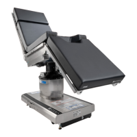
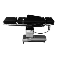
Figure 3-2. Connect STERIS 4085 General Surgical Table
to Facility Power (Typical)
C-MAX 04
CH
A
RG
E
BA
T
T
E
R
Y
IN
T
E
L
L
I
P
O
W
E
R
OFF
ON
Ensurecapscover
socketswhennotin use.
SERVE
0 I
0 I