7-5
764333-766
11. Secure lower cover to base using four existing
fasteners.
12. Secure base cover to base using screw and spacer.
13. Ensure telescoping column covers move
smoothly and do not separate during operation.
14. After applying RTV, remove any excess sealant
using an alcohol dampened rag.
15. Allow sufficient cure time as recommended by the
RTV manufacturer before returning table for use.
7.5.2 One-Part Base Cover (Plastic)
1. Seal area where power supply inlet is exposed
through base (see Figure 7-8).
2. Install base cover insert and fasten to base cover (see
Figure 7-11).
Figure 7-11. Install Base Cover Insert and
Attach to Base Cover
3. Apply RTV to seam between base cover insert and
base cover (see Figure 7-12).
Figure 7-12. Seal Seam Between Base Cover
Insert and Base Cover
4. Apply RTV around base perimeter where column
shrouds attach.
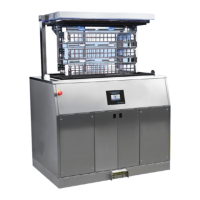
5. Seal around entire perimeter between upper plastic
column covers and column ensuring to fill entire
gap as shown in Figure 7-9. Smooth out RTV as
much as possible.
6. Seal along both seams of upper plastic column
covers as shown in Figure 7-10.
7. After applying RTV, remove any excess sealant
using an alcohol dampened rag.
8. Allow sufficient cure time as recommended by the
RTV manufacturer before returning table for use.
7.6 BATTERY REPLACEMENT
1. Turn Main Power Switch to OFF and remove
battery fuse (refer to supplied Operator Manual for
more information).
2. Remove Table Column Cover (see S
ECTION 7.3,
T
ABLE COLUMN COVER ASSEMBLY).
3. Remove stainless-steel or plastic base cover per
S
ECTION 7.4, TABLE BASE COVER ASSEMBLY, and set
aside in safe location.
NOTE: Before removing battery cables, note position of
cables on the batteries for reattachment.
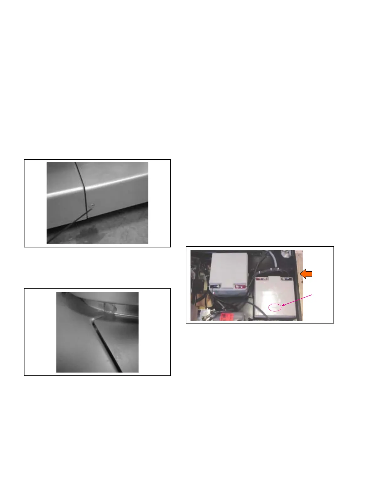
4. Before replacing batteries, verify (see Figure 7-13):
• Same engraved number (typically located on
plastic top of each battery) on both batteries.
Ensure both batteries are manufactured by same
vendor.
• For new batteries, difference in voltage does not
exceed 0.2 V.
5. Reverse procedure to install new batteries.
Figure 7-13. Replace Batteries
7.7 POWER SUPPLY REPLACEMENT
1. Turn Main Power Switch to OFF, remove power
cord (if installed) and remove battery fuse (refer to
supplied Operator Manual for more information).
2. Remove Table Column Cover (see S
ECTION 7.3,
T
ABLE COLUMN COVER ASSEMBLY).
3. Remove stainless-steel or plastic base cover per
S
ECTION 7.4, TABLE BASE COVER ASSEMBLY, and set
aside in safe location.
4. Remove and save Ground Equalization Terminal
(Male Connection) and fender washer from Power
Panel (see Figure 7-14).
5. Remove and save two socket head cap screws
fastening power supply to table frame.