7-4
764333-766
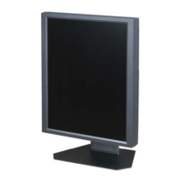
Figure 7-5. Ensure Base Cover Sits Flush on
Base at Insert Opening
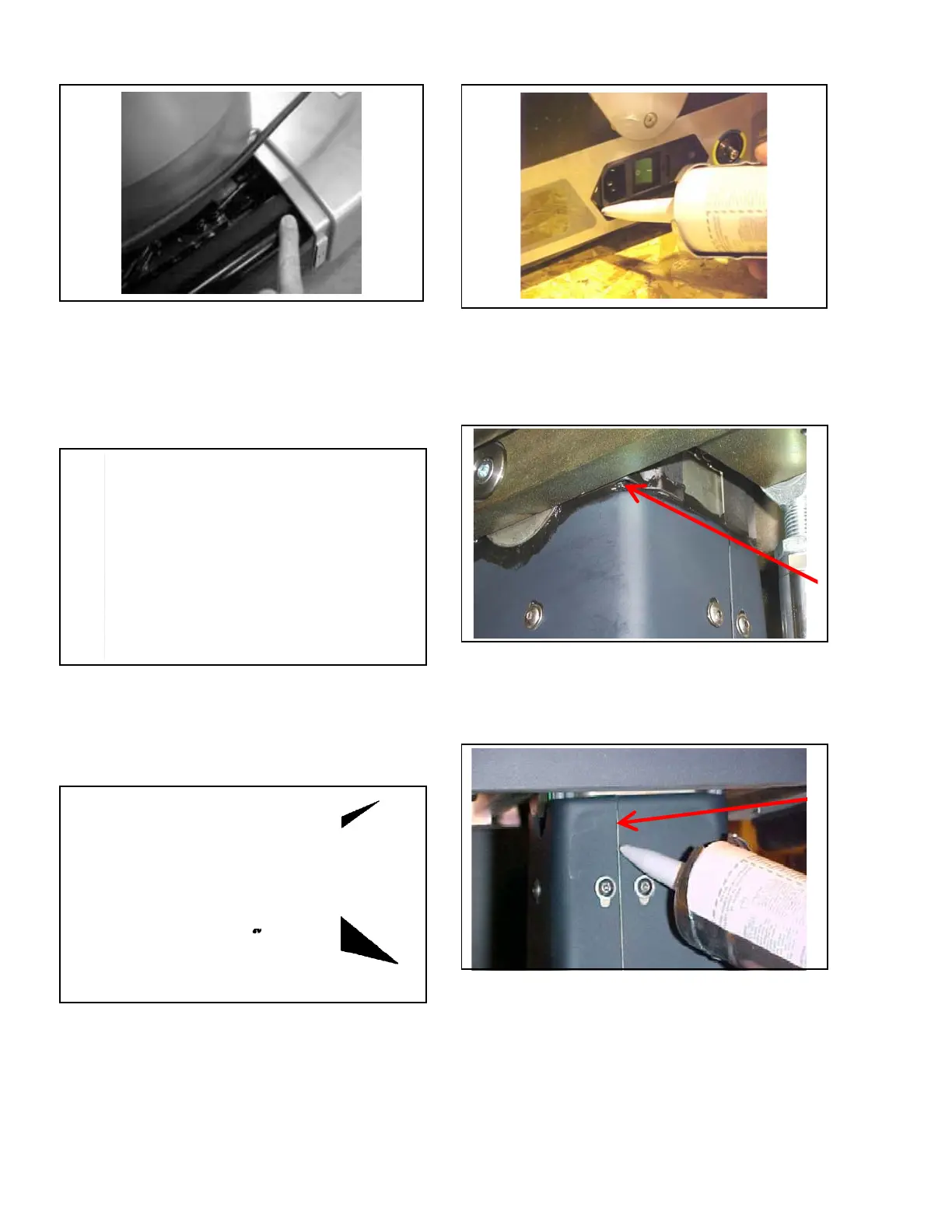
3. Seal mating areas between front and rear base
covers as shown in Figure 7-6.
NOTE: Ensure RTV is applied to both left and right sides
of base covers before assembly.
Figure 7-6. Seal Mating Areas Between Front
and Rear Base Covers
4. Apply RTV to bottom of each V-shaped cut-out
around interface with column covers (see
Figure 7-7).
Figure 7-7. Apply RTV to V-Shaped Cut-Outs
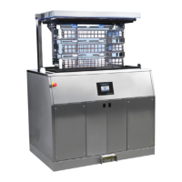
5. Seal area where power supply inlet is exposed
through base (see Figure 7-8).
Figure 7-8. Seal Cover Around Power Inlet
6. Seal around entire perimeter between upper plastic
column covers and column ensuring to fill entire
gap as shown in Figure 7-9. Smooth out RTV as
much as possible.
Figure 7-9. Seal Around Upper Plastic Covers
and Column
7. Seal along both seams of upper plastic column
covers as shown in Figure 7-10.
Figure 7-10. Seal Along Both Seams of Upper
Plastic Column Covers
8. Install lower (inner) column cover around column.
9. Snap halves together and fasten using previously
removed screw. Repeat for all column covers.
10. Secure upper (outer) cover to bracket using six
existing fasteners.