3-4
764333-766
control (optional) and table sensors. A DSP (Digital Signal
Processor) is the heart of the master controller, with
software stored internally using Flash ROM. Solenoid
outputs are generated by open-collector drivers. A
watchdog timer and appropriate software monitor I/O
signals to ensure graceful (instant) recovery should the
I/O ports become configured in an erroneous state.
Feedback on the state of each output goes back to the
microprocessor. If any output is turned on the DSP can
issue an alarm indication (service wrench displayed on
LCD) and if required, automatically turn the table OFF.
Voltage of the Battery charger, Battery and Battery
balancing is continuously checked and adjusted. If any
voltages are out of limits an alarm is displayed. Battery
condition is continuously displayed through icons on the
LCD display and LEDs on battery charger display located
on the table base. The power supply controller determines
when to supply battery power or facility power to the
table master control. The master control board reads the
power status from the power supply and displays icons
on the Hand Control to show the power state (facility
power or battery).
The hand control DSP is similar to the Master controller
in that the software is stored internally in Flash
EPROM. Master Control can be erased and
reprogrammed with a service utility program
communicating with a PC (laptop computer), or at the
PCB manufacturer. IC replacement is not an option for
reprogramming. Both DSPs use a hardware watchdog
timer and resets if conditions arise that indicate the
software routines are not running correctly.
The Master controller has a RTC (Real Time Clock) that
is programmed at the factory. The time is used to time
stamp events that are stored in an Event Log that is
viewable and retrievable by a factory-trained STERIS
Service Technician. The time and date is set to GMT
(Greenwich Mean Time) sometimes called UCT
(Universal Coordinated Time). The clock should never
be reset to local time so that all data, regardless of world
location has the same time reference, eliminating errors
of time zones and daylight savings time. A set of counters
is also maintained that increment every time a fault has
repeated. The Log and timer can also be downloaded by
a factory-trained STERIS Service Technician to a laptop
in a .csv (Comma Separated Values) File format. The file
can be sent to specialists in order to assist in
troubleshooting. The csv file can be viewed with any text
viewer or spreadsheet program such as Microsoft Excel
®1
.
1
Excel is a registered trademark of Microsoft Corporation.
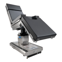
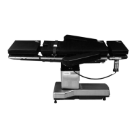
3.4.2 System Function
1. Table Control Board Description:
a. Two master control boards are possible. The
earlier version (P542200-903) is a dedicated use
Cmax
™
110 NA control. The newer version
(P150832-769) may be configured for either the
Cmax 110 NA, the 4085 General, the 5085 General
or the 5085 SRT Surgical Table by DIP switch
settings. The required settings are stenciled on
the control board cover (see
Table 3-1)
.
b. Control software resides in two places. One
program is in the table control board and a
separate program resides in the hand control.
The earlier version master control board
program may be downloaded using Cmax 110
Flash Loader 1.0. The newer version is
downloaded using the diagnostic utility called
Cmax Service 1.8 or higher.
c. For compatibility between old/new controls
and hand controls, see Table 3-1. Sensor
calibration is not the same for both versions.
Default calibration values may not be pre-
loaded in the software.
d. The control board contains a battery that
supports the RTC kernal clock. See appropriate
paragraph of S
ECTION 3.4.1, OVERVIEW, for
more information.
e. Three LEDs are visible on the control cover to
indicate a heartbeat (medium rate flashing
green light), a busy state (fast flashing green
light) and an error condition (red light). The
yellow LED is a control panel ON indicator.
2. Power Supply and Battery Charger (internal and
external accessible fuses):
a. Voltage of the Battery Charger, Power Supply,
Hydraulic and Slide functions is explained in
S
ECTION 3.4.1, OVERVIEW.
b. Input line power is protected by fuses F6 and
F7 in the power entry module in the power
supply. Power switch (green backlighted) must
be closed ( " | " symbol for ON position) to
activate the battery charger.
NOTE: The power supply has an onboard
controller that communicates with the table
control board at P6. It performs various
housekeeping functions such as monitoring
battery levels and charger and battery faults.
These types of faults may appear on the main
hand control as a service wrench display but
are otherwise not available for troubleshooting
purposes.
c. Battery power is protected by fuse F8 which is
located next to the foot pedal. It is in series with
(in between) the two batteries.