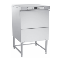
Fig. 10
3. Slide control cover forward and disconnect
switch membrane ribbon cable from connector.
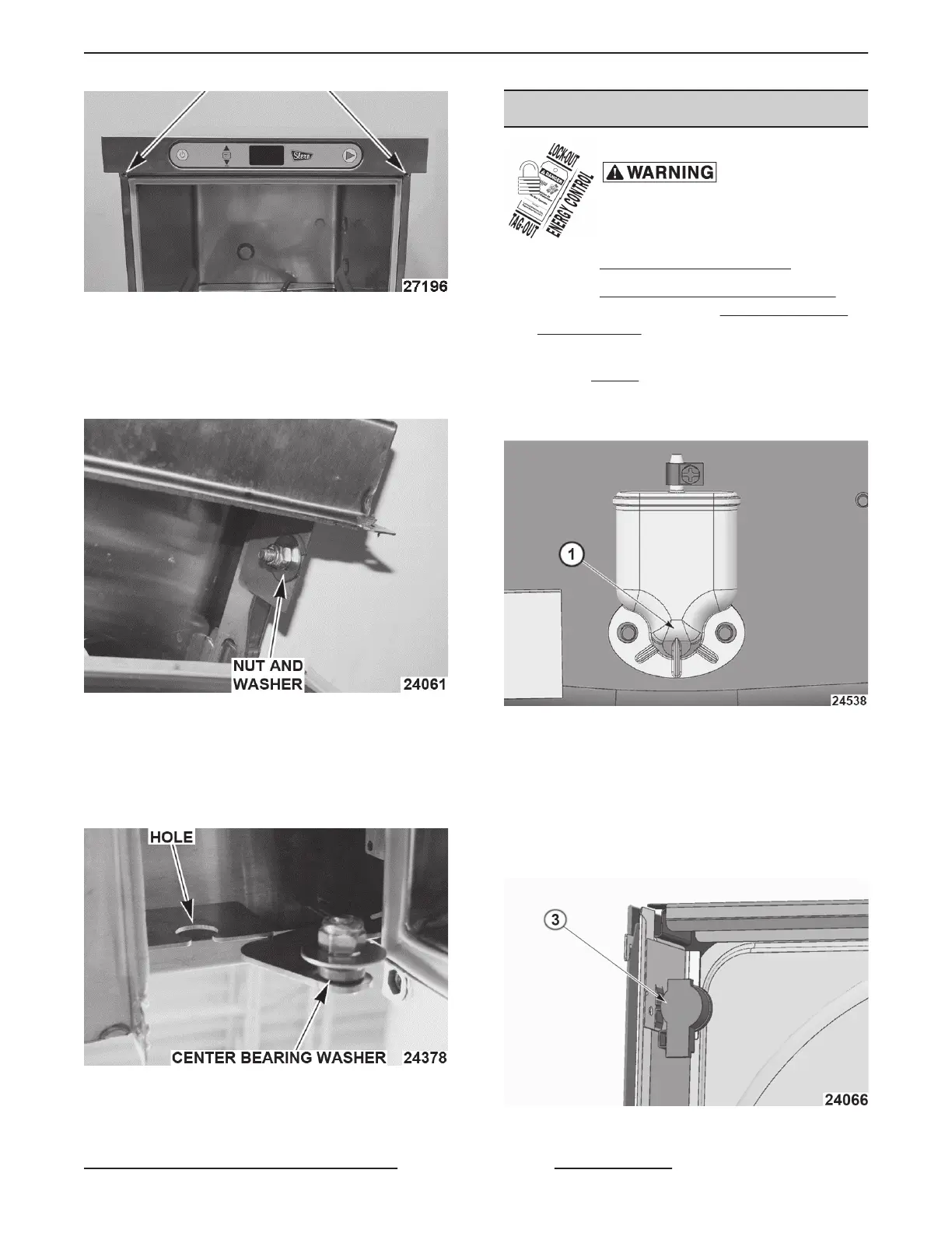
4. Loosen nut, washer and center bearing washer
from both sides. (Do NOT remove hardware)
Fig. 11
5. Remove control cover.
6. Reverse procedure to install.
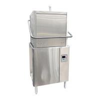
NOTE: Center bearing washer must be centered in
hole to allow rotation.
Fig. 12
7. Check for proper operation.
WATER LEVEL SENSORS
Disconnect the
electrical power to the machine and
follow lockout / tagout procedures.
1. Remove
CONTROL PANEL COVER.
2. Remove
LEFT AND RIGHT TRIM PANELS
(Booster/Holding Tank) or LEFT AND RIGHT
TRIM PANELS (Sump tank).
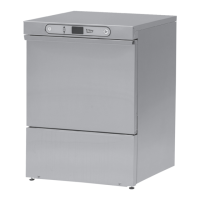
3. Drain sump or Booster/Holding tank below air
trap (1, Fig. 13) inlet.
NOTE: Not draining sump or booster / holding tank
may cause a leak.
Fig. 13
4. Disconnect water level cable from sensor and
tube clamp.
5. Push plastic tabs (using screwdriver or pliers) to
remove.
NOTE: Do NOT over squeeze pinch clamps on
bottom of sensors.
Fig. 14
SG, SU-L, SU-H DISHWASHERS - REMOVAL AND REPLACEMENT OF PARTS
Page 9 of 59 F45577 (1215)