Online version - not for reprint
102 MS 341, MS 361, MS 361 C
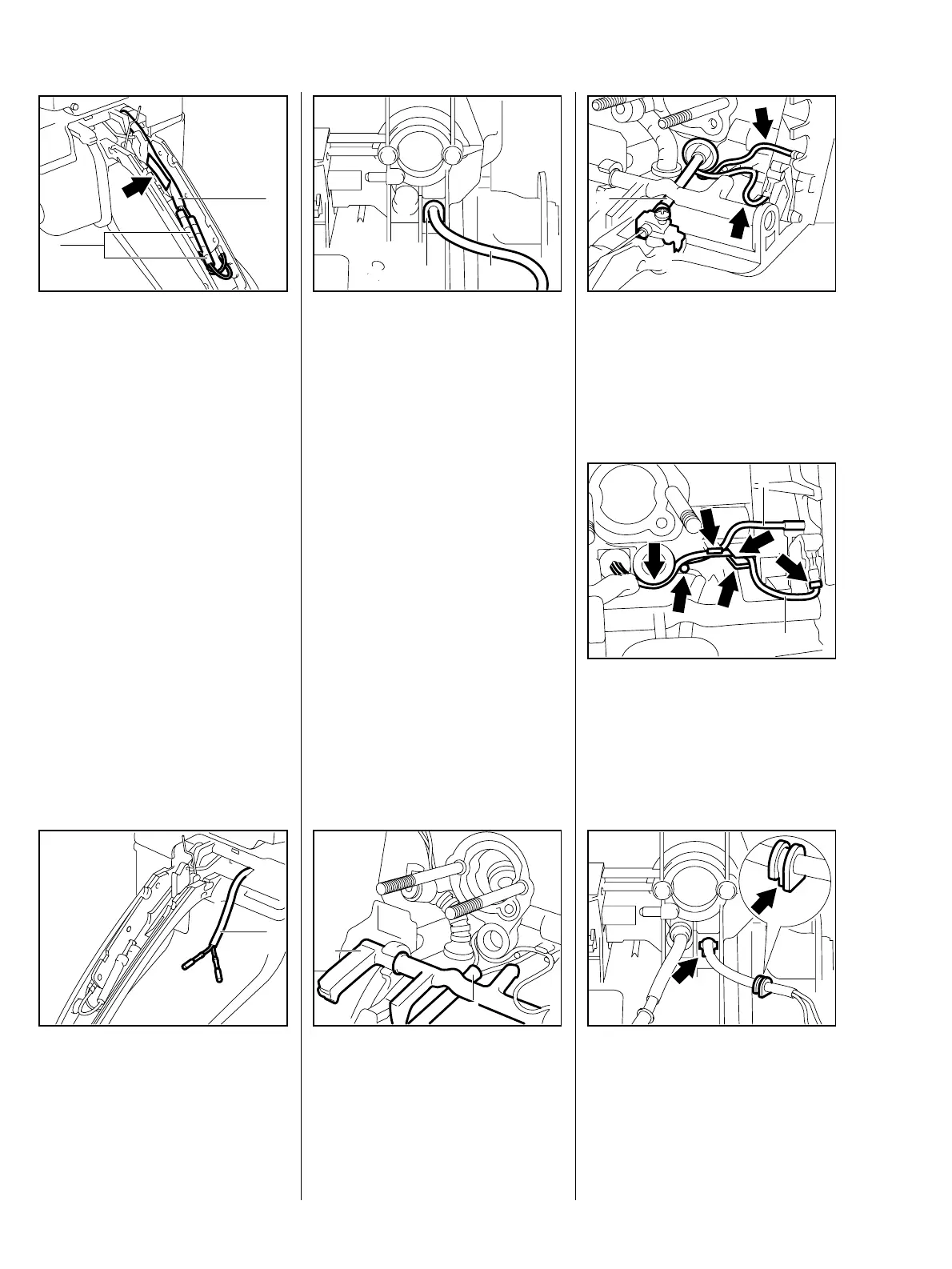
– Remove the interlock lever – b
10.2.1 or 10.2.2
: Remove the wire (1) from the
guide (arrow).
: Push back the insulating tubes
(2) and separate the connectors.
VA
212RA244
1
2
: Pull the wires out of the insulating
tube (1).
VA
212RA245
1
: Pry out the grommet (1).
: Pull out the wires (1).
– If necessary, remove the front
handle with handle heating –
b 14.5
VA
212RA239
21
– If necessary, remove the heater
switch – b 14.6
Install in the reverse sequence.
: Position wires (1) under the
switch shaft (2).
VA
212RA246
1
2
On machines with
QuickStop Super
: Position the wires (arrows) under
the brake cable (1).
VA
212RA240
1
: Make sure the ground wire (1)
and short circuit wire (2) are
correctly positioned (see arrows).
212RA308
VA
1
2
Check correct installed position of
the grommet (arrows).
Install all other parts in the reverse
sequence.
VA
212RA241

 Loading...