Online version - not for reprint
67MS 341, MS 361, MS 361 C
– Remove the crankcase from the
tank housing – b 12.9
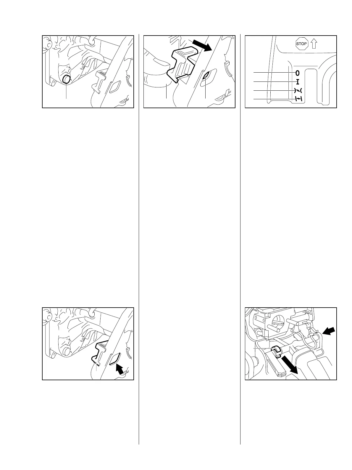
: Use a suitable tool to pry the stop
buffer (1) out of the crankcase.
– Lubricate the new stop buffer with
STIHL Press Fluid OH 723 –
VA
212RA134
1
b 16.
– Push the stop buffer (1) into the
crankcase as far as stop.
Reassemble all other parts in the
reverse sequence.
: Use a suitable tool to pry the stop
buffer (1) out of the crankcase.
VA
212RA135
1
– Lubricate the new stop buffer with
Press Fluid OH 723 – b 16.
: Push the stop buffer into the
housing until its groove (1)
engages over the inner housing
rib (2).
VA
212RA136
1
2
Reassemble all other parts in the
reverse sequence.
The Master Control lever moves the
switch shaft to select the required
function.
The following positions can be
selected with the Master Control
lever:
VA
212RA116
1
2
3
4
“STOP“ (1) closes short circuit
contact, interrupts ignition
“RUN“ (2) is the normal operating
position
“START“ (3) is the starting throttle
position / choke shutter open (warm
start)
“CHOKE“ (4) is the starting throttle
position / choke shutter closed (cold
start)
: Carefully ease the switch shaft
out of its left-hand mount (1) and
then pull it out of the right-hand
mount (arrow).
VA
212RA117
1
9.1.4 Stop Buffer between
Crankcase and Tank
Housing
10. Master Control /
Handle System
10.1 Switch Shaft

 Loading...