26
03.11
Strapex SMA 30
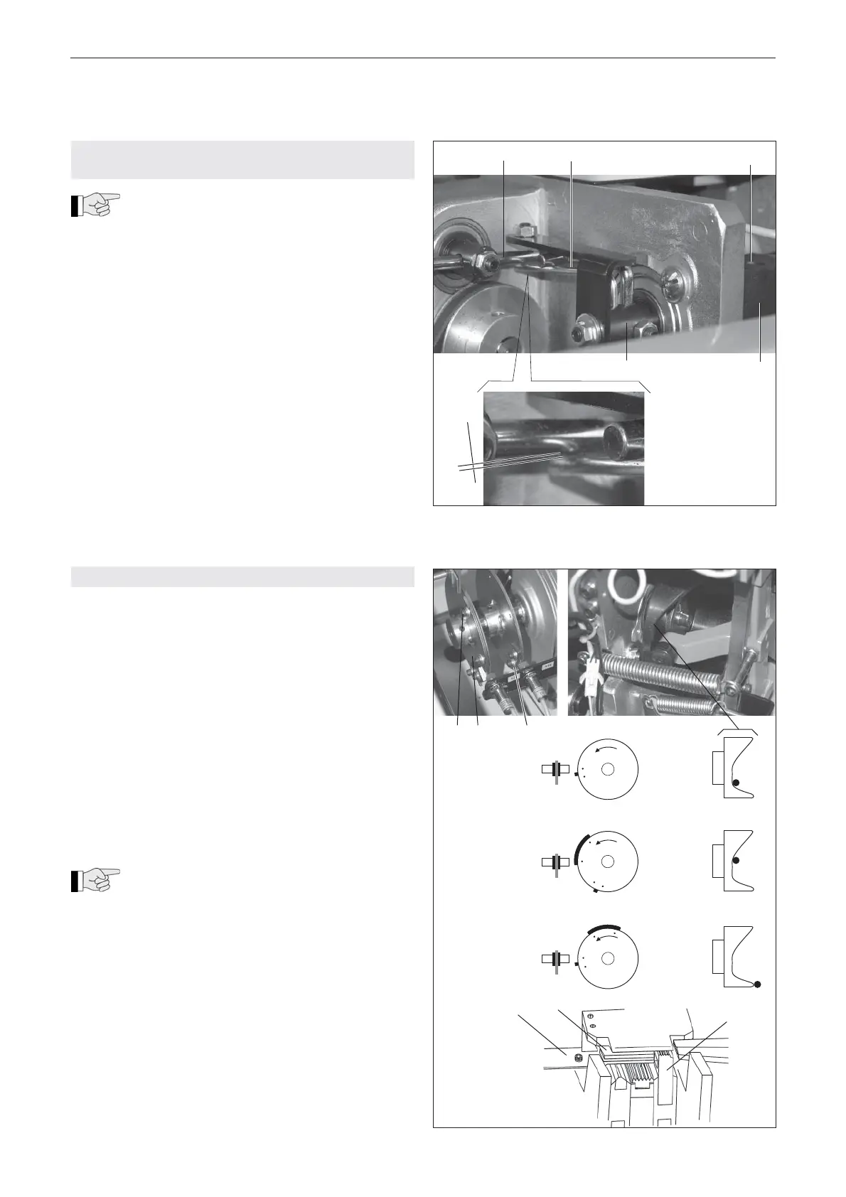
9.4 SET DISTANCE BETWEEN TRANSPORT
AND PRESSURE ROLLER
The distance between the transport and
pressure roller is adjusted to strap thickness
of 0.55-0.65 mm. If the thickness varies, the strap
feed may not function correctly. The distance must be
set as following:
– Turn main switch (3/1) to position ”1“.
– Press the ”Reset” button (3/6) to move the machine
to its initial position.
– Insert strap to be used between transport and
pressure rollers.
– Loosen two cylinder screws (14/3), hold right clam-
ping lever (14/4) in position. Now the guide shaft
(14/5) can be turned by hand until the clearance
between torsion spring (14/2) and threaded bolt
(14/1) is about 1 mm.
– Tighten cyclinder screws (14/3) again.
Fig. 14
1 2 3
4 5
1 mm
9.5 ADJUST LIMIT SWITCHES (CONTROL CAMES)
Initial position
The setting ”Initial position” is performed by limit switch
S48.
– Turn aggregate on drive belt of motor M23 by hand
so that the cam disk turns in direction of arrow (see
Fig. 15). Turn aggregate so that the radial cam is in
position A. Loosen two screws and turn cam element
(15/3) so that the cam is directly poitioned below the
limit switch S48 (see Fig. 15).
Strap take up
The setting ”Strap take up” is performed by limit switch
S39. (cam disk 15/2).
– Turn aggregate so that the radial cam is in position
B. Turn cam disk (15/2) so that the cam has directly
passed the limit switch S39 (see Fig. 15).
During this cycle the right-hand press unit
(15/4) moves up and clamps the strap. The
slide plate (15/5) moves backwards and the guide fl ap
(15/6) is opened.
Strap feed
The setting ”Strap feed” is performed by limit switch
S39. (cam disk 15/1).
– Turn aggregate so that the radial cam is in position
C. Turn cam disk (15/1) so that the cam has directly
passed the limit switch S39 (see Fig. 15).
Initial position
Strap take up
Strap feed
S48
S39
S39
A
1 2 3
B
C
4
5
6
Fig. 15