38
S
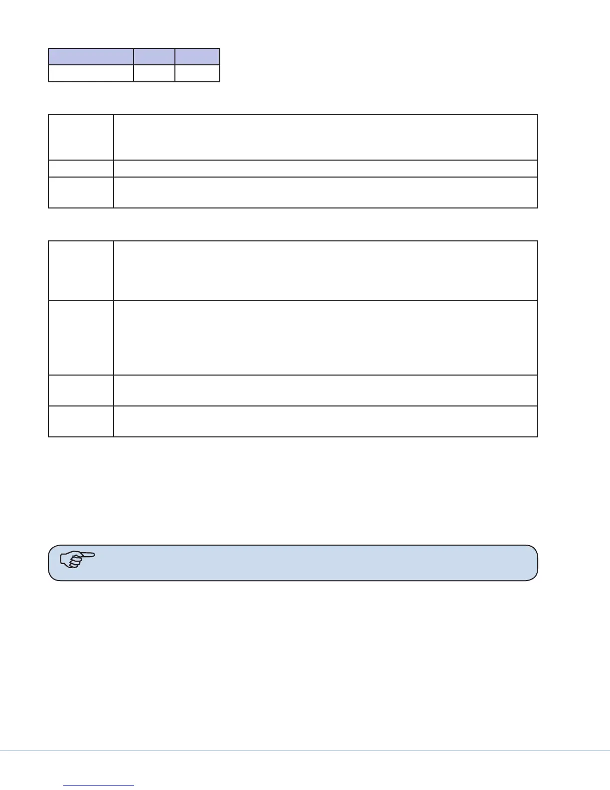
ITEM-ITEM QTY SIZE
WRC/CRC – *
1
¾"
10.1.2.4 Touchpanel
Conduit e control cable must be run to the touchpanel location with a 15' (4.5m) service loop.
Conduit required to pull the cables listed below will be determined by the Hospital/
Contractor.
Power One (1) electrical wall outlet adjacent to the empty junction box.
Cabling One (1) Belden 8723 or 88723 cable from the junction box to the controller (maximum
300' [91.5m])
10.1.2.5 All Displays
Conduit e signal cable must be run from the system controller to a double gang junction
box with single gang mud ring ush mounted in the wall directly above the mount-
ing bracket with a 15' (4.5m) service loop. Conduit required to accomplish this will be
determined by the Hospital/Contractor.
Structural Hospital/Contractor to mount the Stryker provided mounting bracket to the wall (for
40" LCD option) in the desired location with proper reinforcement to support the cor-
rect display before Stryker installation. e mounting bracket and instructions will be
delivered with the LCD. (See Appendix A for equipment weight, power, and dimension
specications.)
Power One (1) standard electrical outlet mounted adjacent to the empty junction box. (See
Appendix A for power consumption.)
Cabling One (1) Belden 8241 or 88241 (or equivalent) from the display to the controller (maxi-
mum 1000' [305m])
10.2 SuiteStatus Systems
e SuiteStatus System combines the Fixed, IP Camera video signals from separate rooms into one
display located at the OR Control Desk. All video feeds will be sent over a provided network, using the
Internet Protocol standard, and are accessible from up to three All-In-One Computer Systems. is
section describes site preparation requirements necessary prior to the installation phase of the SuiteS-
tatus System.
Note All networking requirements should be met prior to Stryker’s arrival for installa-
tion.

 Loading...


