928 Mixing Console
Operation E 2/3Edition: 07.02.01
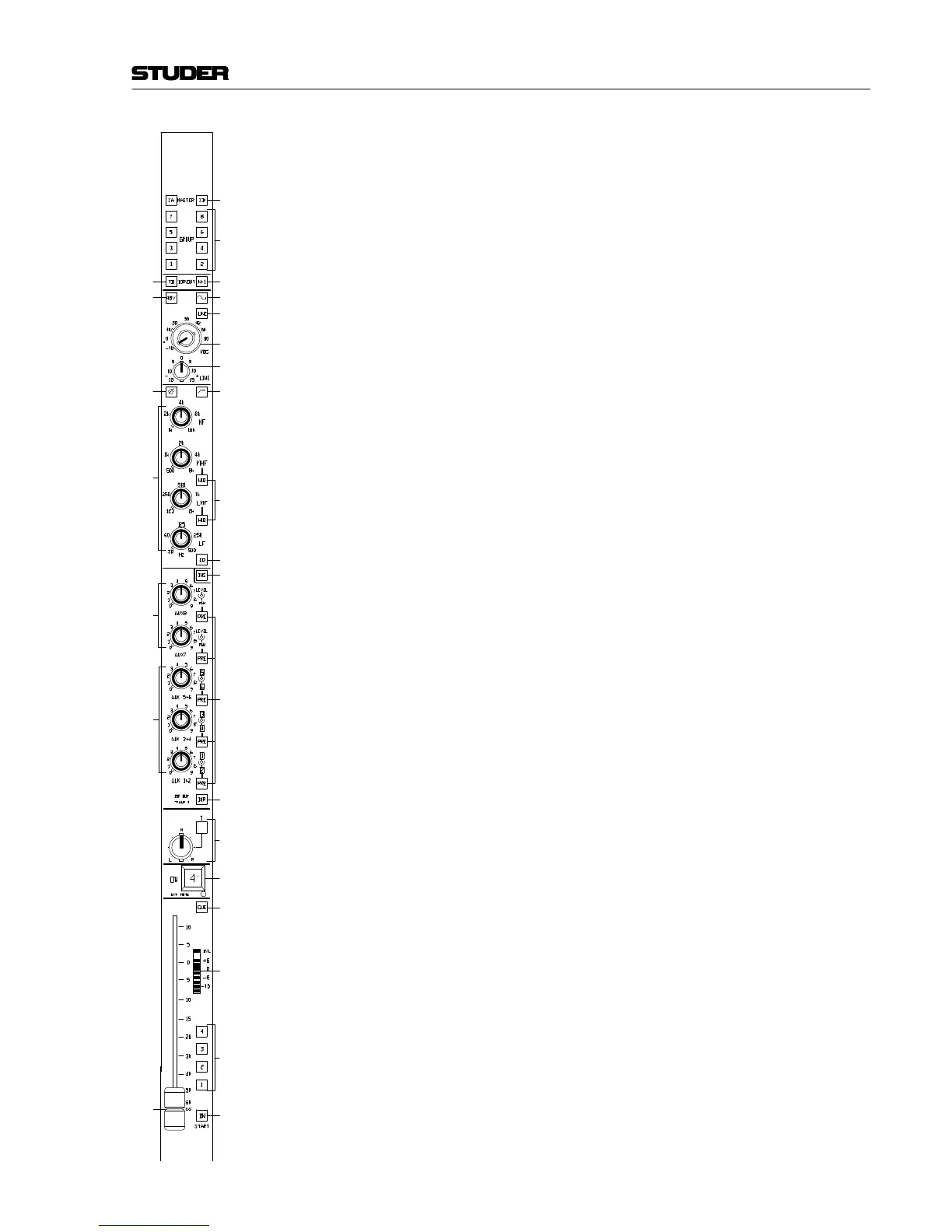
[16] AUX 7, AUX 8
Outputs to the stereo auxiliary busses 7 and 8. The (pre- or post-fader)
input signal can be mixed to the desired AUX bus with the concentric
potentiometers. The small knobs are the level controls, while the outer
rings are used as PAN controls.
[17] AUX 1+2, AUX 3+4, AUX 5+6
Outputs to the mono auxiliary busses 1...6. The (pre- or post-fader)
input signal can be mixed to the desired AUX bus with the concentric
potentiometers; the knobs are the level controls for the odd-numbered
AUX busses (1, 3, 5), the outer rings for the even-numbered AUX
busses (2, 4, 6).
[18] PRE
If PRE is pressed, the pre-fader signal is mixed to the AUX bus instead
of the post-fader signal, and the key is illuminated.
[19] DIR
Key for inserting the AUX 1 potentiometer into to the direct output or
N–1 path (DIR OUT). If this key is pressed, the AUX 1 output is muted.
[20] PAN TO GROUPS
Panorama potentiometer with detent in center position. For position-
ing the mono input signal within the stereo image of the ΣA and ΣB
main mixes (MASTER), regardless whether the adjacent PAN key is
pressed or not.
If the PAN key is not pressed, the channel signal is routed in mono to
all Groups. If it is pressed (and illuminated), the pan pot splits the sig-
nal into left and right outputs which are routed to the odd- and even-
numbered Groups respectively.
[21] ON
Key for activating the channel with the possibility of external control.
The EXT MUTE LED below the key is on if MUTE is externally control-
led via the remote input.
[22] CUE
Key to activate the CUE function. If the key is pressed for a short time
(less than 0.5 s), the function latches; if the key is pressed for more
than 0.5 s, it is used as a momentary pushbutton, and the function will
be reset after the key has been released.
If the CUE function is activated while the fader is set to its –∞ position,
the AFL/PFL signal is connected to the CUE bus, depending on the
AFL/PFL setting made on the CR Monitor Unit. The function will be
reset as soon as the fader is moved away from the –∞ position.
[23] LED bargraph with OVL LED
The point to be monitored with the level meter can be selected with
jumpers from pre-EQ, post-fader, or direct output/N–1. The meter char-
acteristics can be jumper-selected from PPM or VU. (For jumper set-
tings: refer to section 3.1.1).
The OVL LED monitors pre-EQ, post-EQ, and post-fader; if any of these
points reaches a level of 6 dB below clipping, the LED comes on.
PAN
PAN TO GROUPS
[4]
[3]
[1]
[2]
[5] [6]
[7]
[10]
[8]
[9]