© STULZ GmbH, Hamburg EN / 10-2015 / 1000683
-
53
-
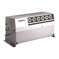
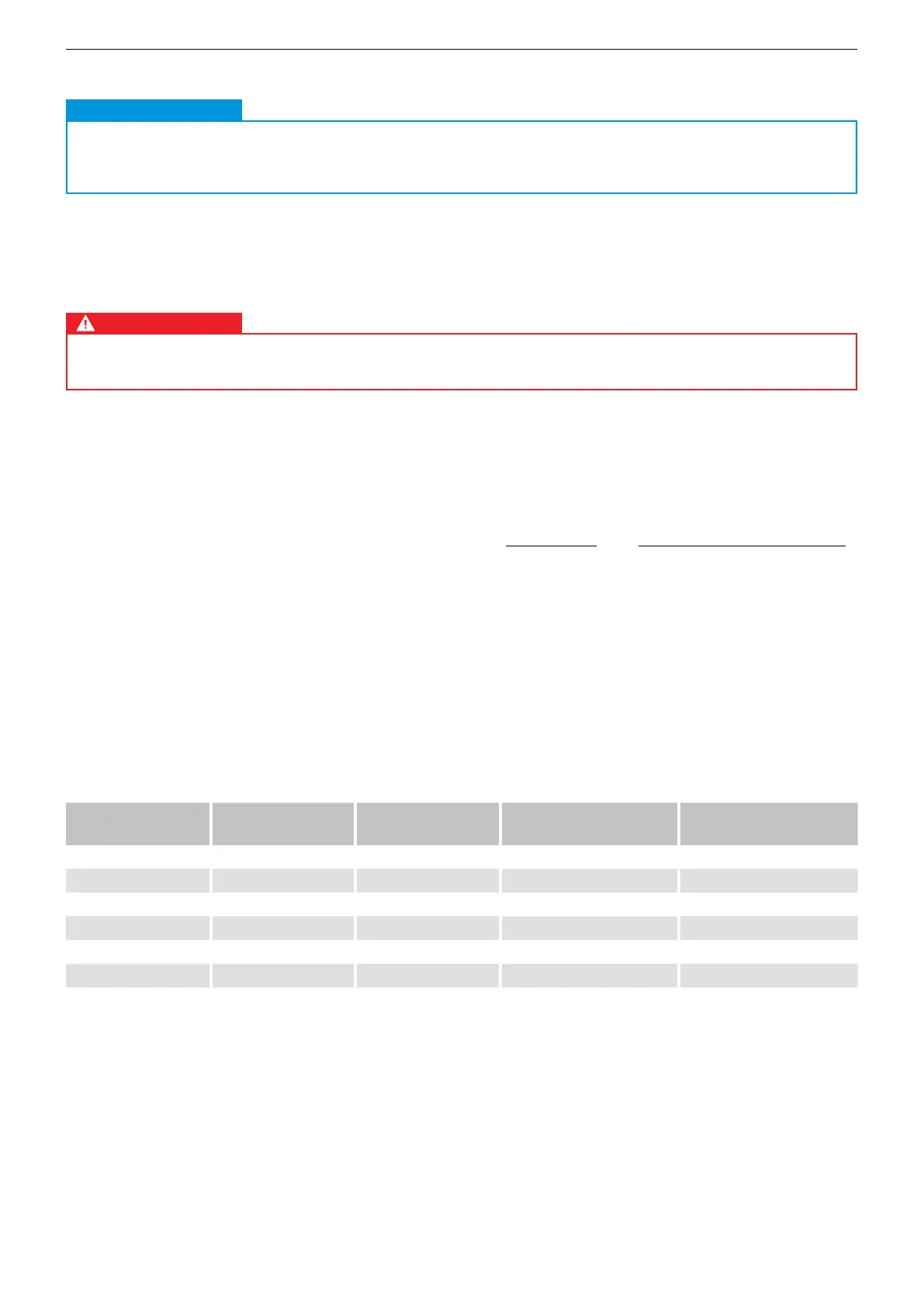
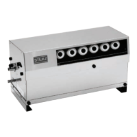
STULZUltraSonic-SystemforDirectRoomHumidicationBNB- Installation
7.5.2. Cable dimensions
The connecting cable bet
ween th
eultrasonichumidierandthecontrolbox(transformer)reducesthe
voltageattheultrasonichumidieraspertheformulasbelow:
i = Voltage drop [V]
L = Cable length [m]
I = Current [A]
A = Cable cross-section [mm²]
ϒ= Electricalconductivity[m/(Ω x mm
2
)]
Note:56.2[m/(Ω x mm
2
)]forcopper
(4%of48VACelectricalsupply,i.e.maximumvoltagedrop1.92V.Thisresultsinaminimumpermitted
electricalsupplyof46.08VAC).
If the voltagedropbetweenthecontrolcabinetandtheultrasonichumidieris4%orlower,thevoltage
is still within tolerance. If the voltage falls below this value, however, please select a larger cable cross-
section with the aid of the table.
Type Electrical
supply
Current Maximum cable length
(1.5 mm²)
Maximum cable length
(2.5 mm²)
BNB 1000 A 48 V AC 2.08 A 39 m 65 m
BNB 2000 A 48 V AC 3.75 A 22 m 36 m
BNB 3000 A 48 V AC 5.2 A 16 m 26 m
BNB 4000 A 48 V AC 7.08 A 12 m 19 m
BNB 5000 A 48 V AC 8.96 A 18 m 30 m
BNB 8000 A 48 V AC 13.96 A 12 m 19 m
7.5.1.3. Connection of humidi er accessory sets
CAUTION
Connection of accessory sets.
To connect accessory sets, please pay attention to the circuit diagrams in the technical
documentation for accessory sets.
Note
CAUTION
Danger of death. Electric shock risk.
The cable dimensions must be calculated by expert personnel.
WARNING
DANGER
2 x L x I
i =
ϒxA
2 x L x I
=
56.2
[m/(Ω x mm
2
)]
x A