95
June 2013
Electrical Systems Operation & Diagnosis Module (602)
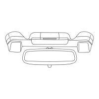
The speed and rotation of the output shaft is monitored with a hall effect switch assembly. The
center rotor is comprised of permanent magnets that are arranged with alternating poles that
interface with the hall effect switch assembly as the output shaft rotates. The output can be viewed
on the Subaru Select Monitor as “Pulse Count”.
Pulse Count Sensor Sensor A and B
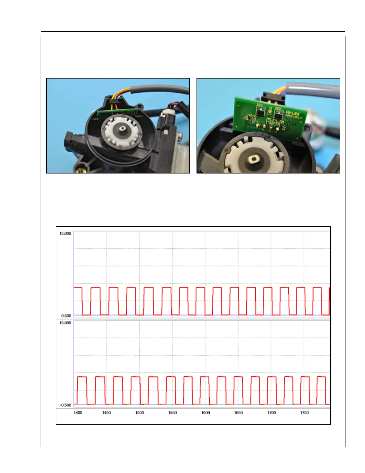
The two signals are inputs to the PRG control unit. Sensor A and sensor B, as described in the
I/O chart, range from 0 to 5 volts with the PRG in motion. A failure with either signal results in a
DTC and PRG functions will be cancelled.
Sensor A and B Output
196 197
198