Zero point clamping
SEMOD54417-137 v4
Measured value below zero point clamping limit is forced to zero. This allows the
noise in the input signal to be ignored. The zero point clamping limit is a general
setting (XZeroDb where X equals S, P, Q, PF, U, I, F, IL1-3, UL1-3, UL12-31, I1,
I2, 3I0, U1, U2 or 3U0). Observe that this measurement supervision zero point
clamping might be overridden by the zero point clamping used for the
measurement values within CVMMXN.
Continuous monitoring of the measured quantity
SEMOD54417-140 v5
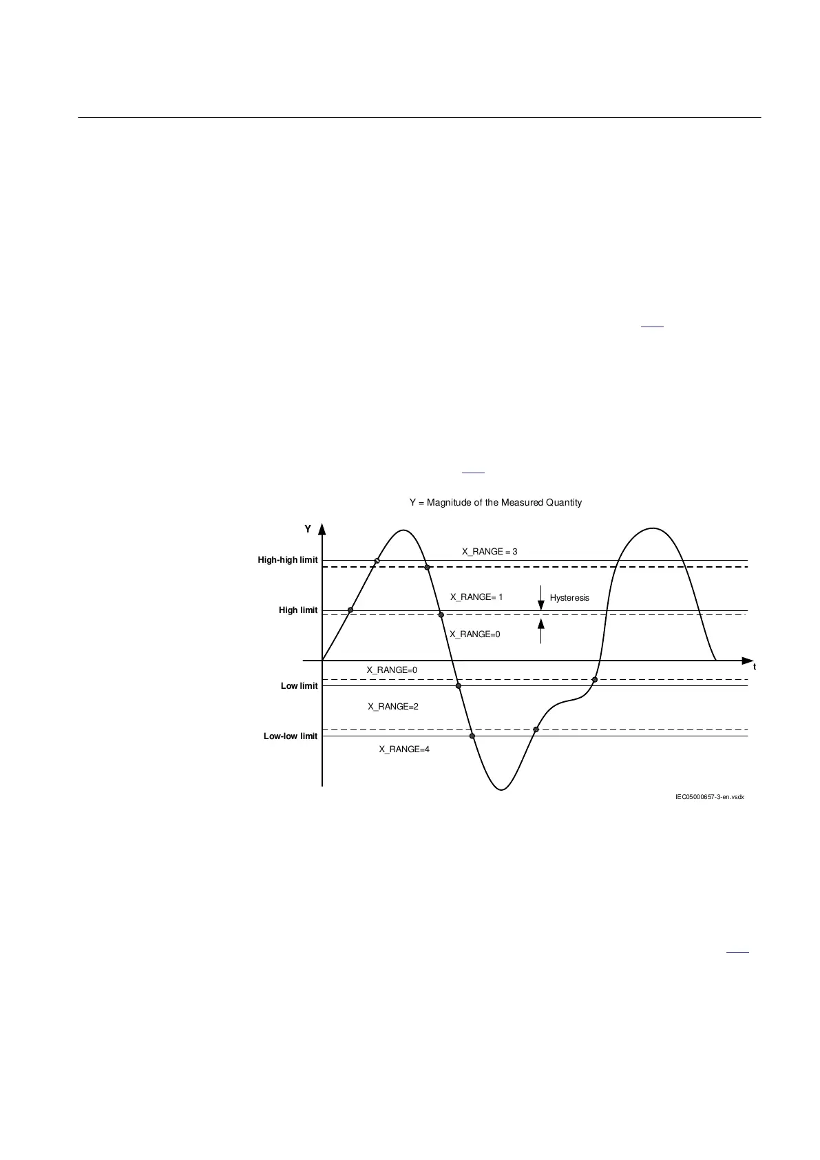
Users can continuously monitor the measured quantity available in the function
block by means of four defined operating thresholds, see figure 197. The
monitoring has two different modes of operating:
• Overfunction, when the measured quantity exceeds the High limit (XHiLim) or
High-high limit (XHiHiLim) pre-set values
• Underfunction, when the measured quantity decreases under the Low limit
(XLowLim) or Low-low limit (XLowLowLim) pre-set values.
X_RANGE is illustrated in figure 197.
IEC05000657-3-en.vsdx
X_RANGE= 1
X_RANGE = 3
X_RANGE=0
Hysteresis
High-high limit
High limit
Low limit
Low-low limit
X_RANGE=2
X_RANGE=4
Y
t
X_RANGE=0
Y = Magnitude of the Measured Quantity
IEC05000657 V3 EN-US
Figure 197: Presentation of operating limits
Each analogue output has one corresponding supervision level output
(X_RANGE). The output signal is an integer in the interval 0-4 (0: Normal, 1:
High limit exceeded, 3: High-high limit exceeded, 2: below Low limit and 4: below
Low-low limit).
The logical value of the functional output signals changes according to figure
197.
The user can set the hysteresis (XLimHyst), which determines the difference
between the operating and reset value at each operating point, in wide range for
1MRK 505 384-UEN A Section 11
Monitoring
Breaker protection REQ650 2.2 IEC 413
Technical manual