CheckPoint Pharma and CheckPoint
e
Operation and Maintenance Manual
SUEZ © 2018 49 of 112 DLM 97200-03 EN Rev. A
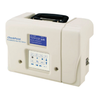
Figure 5: Cover Screw Sizes and Locations
4. Wearing an ESD strap (one is provided in the Accessories Kit), disconnect the three wires in the
power entry module from the Sensor:
• Pull the two connectors out from the left side of the fuse holder.
• Using a 3/8 in. nut driver, loosen the nut to remove the ground wire.
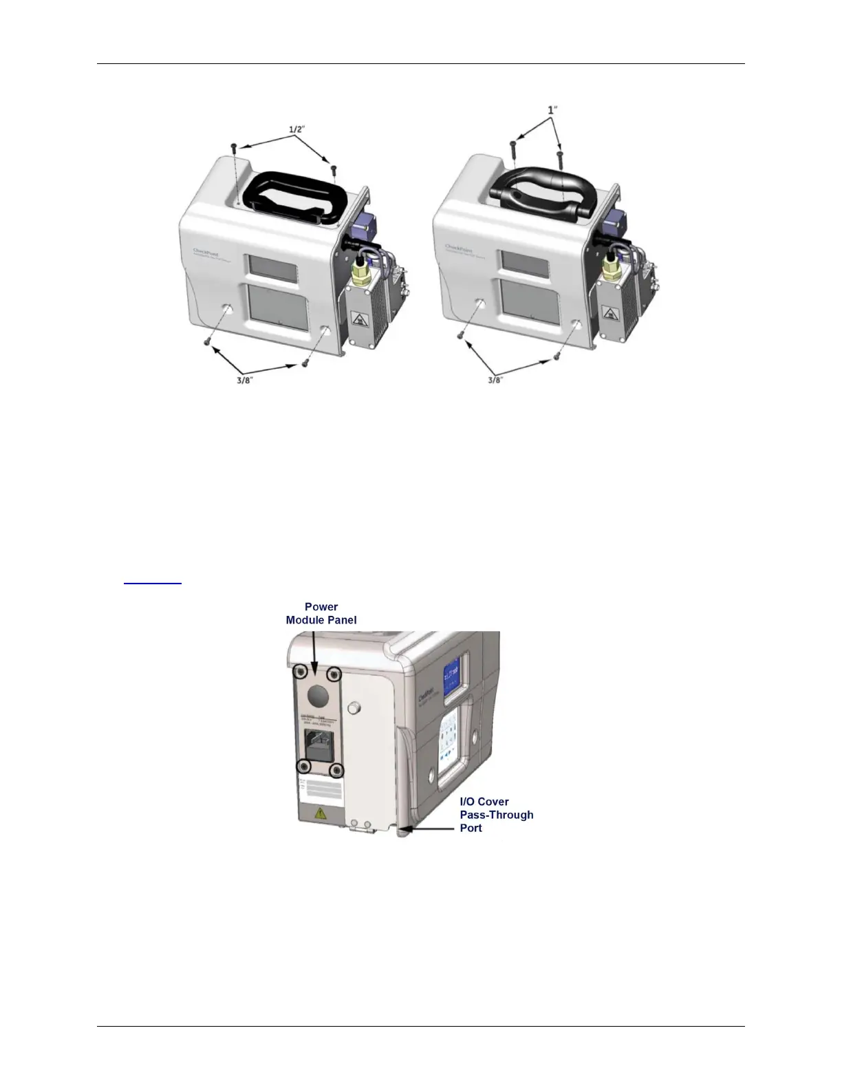
5. Loosen the four screws on the power module panel and remove the panel from the Sensor (see
Figure 6: The Default Power Module Panel and I/O Cover).
Figure 6: The Default Power Module Panel and I/O Cover
6. Attach the new power module panel to the Sensor by securing the screws. Make sure the panel is
correctly positioned. The labels should be right-side up so that they are readable.
In the pass-through port, use a watertight sealing device (or strain relief hub) that is appropriate
for your environment.