CheckPoint Pharma and CheckPoint
e
Operation and Maintenance Manual
SUEZ © 2018 54 of 112 DLM 97200-03 EN Rev. A
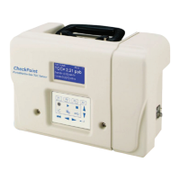
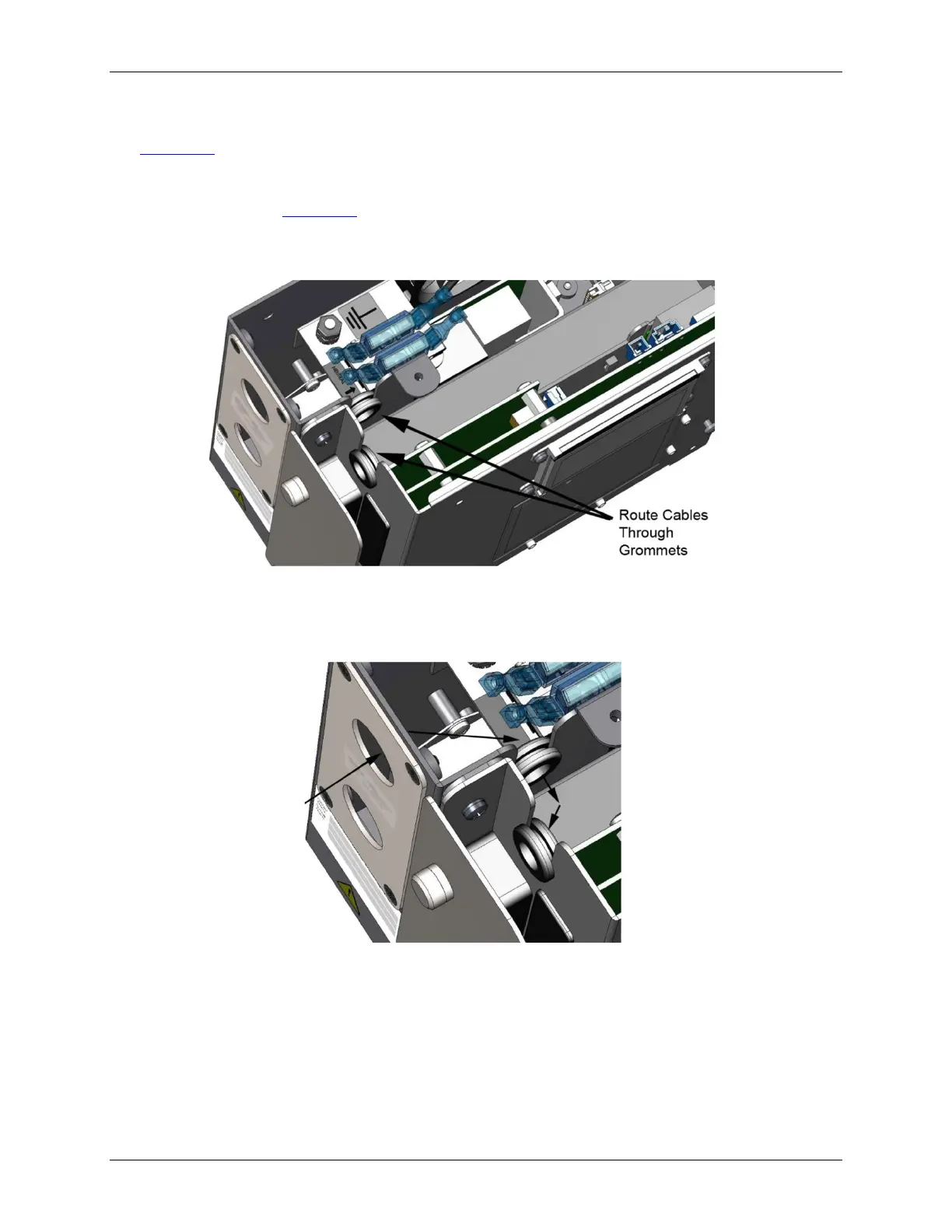
3. Route the I/O cables into the Sensor through the power module panel pass-through port. See
Figure 13: Routing the I/O Cables (Detail).
4. Route the cables through the first grommet and then through the second grommet, to the I/O
terminal blocks (see Figure 12: Routing the I/O Cables). If needed, you can cut a notch in the
grommets to make wire manipulation easier.
Figure 12: Routing the I/O Cables
Figure 13: Routing the I/O Cables (Detail)
5. For 4-20 mA, binary input, and alarm wiring, connect the wiring to the appropriate pins. Consult
the tables below for pin functionality on each terminal block.
Wire should be 22-12 AWG, rated to 300 Volts. Strip length should be 8-9 mm (.33 in). To attach
the output connections, first remove the terminal block from the I/O board by firmly grasping the