26 Sun Fire T1000 Server Installation Guide • January 2006
■ 9600 baud
■ 8 bits
■ No parity
■ 1 Stop bit
■ No handshaking
2. Turn on the terminal or the terminal emulator, if it is not already turned on.
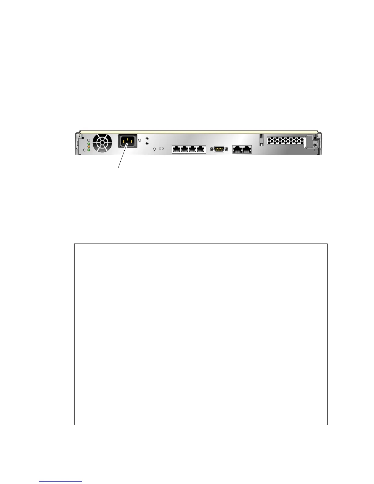
3. Connect the AC power cable and watch the terminal for system messages.
FIGURE 3-1 AC Connector
After the system controller boots, the system controller login prompt is displayed on
the serial console. The following example shows a partial output from the system
controller boot sequence leading to the login prompt.
CODE EXAMPLE 3-1 Excerpt of a System Controller Boot Sequence
Enter #. to return to ALOM
SC Alert: Host System has Reset
0:0>
0:0>@(#) ERIE Integrated POST 4.x.0.build_12-erie 2005/06/14 12:19
/export/common-source/firmware_re/ontario-
fireball_fio/build_12/erie-build_12/post/Niagara/erie/integrated
(firmware_re)
0:0>Copyright © 2005 Sun Microsystems, Inc. All rights reserved
SUN PROPRIETARY/CONFIDENTIAL.
Use is subject to license terms.
0:0>VBSC selecting POST MAX Testing.
0:0>VBSC enabling L2 Cache.
0:0>VBSC enabling Full Memory Scrub.
0:0>VBSC enabling threads: f0f0f0f
0:0>Init CPU
0:0>Start Selftest.....
....................
0:0>IO-Bridge unit 1 lpu init test
0:0>IO-Bridge unit 1 interrupt test
0:0>INFO:
AC in
 Loading...


