SUNFAR C300 107
C300 series of non-sensor current vector-control inverter manual
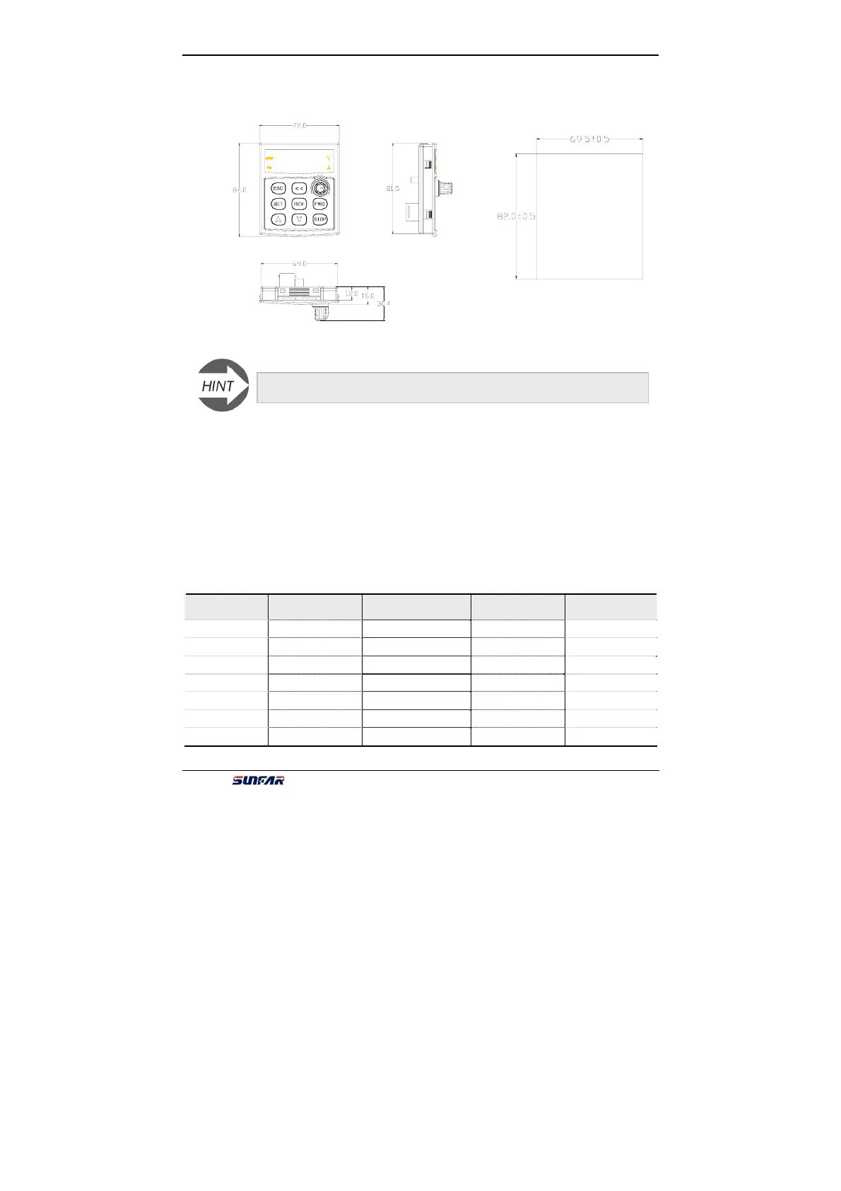
a) Appearance of small panel base
1.3 Installation of panel base
Open a hole on the control cabinet according to dimension of panel base. And put
the panel horizontally into the hole. Then four locks in panel base will lock. There is
an interface on the bottom of base, please insert the long-distance control wire into
it.
2. Brake resistance
The brake resistance is shown following table.
Model
Applied motor
(Kw)
Power of brake
resistance(Kw)
Brake
resistance(Ω)
Brake torque
(%)
C300-2S0002
0.2 0.1 250 100
C300-2S0004
0.4 0.18 150 100
C300-2S0007
0.75 0.25 100 100
C300-2S0015
1.5 0.4 70 100
C300-2S0022
2.2 0.6 50 100
C300-4T0004
0.4 0.25 500 100
C300-4T0007
0.75 0.3 400 100
It is recommended that users take Fig-D Hole dimension of panel base.
Fig-D Hole dimension of small panel base。
Fig-C Dimension of small panel base
 Loading...
