SUNFAR C300 45
C300 series of non-sensor current vector-control inverter manual
6.2 Primary application of parameter unit
0:Constant torque curve
The output voltage of inverter is in direct ratio to the output frequency, and most
load take this mode.
1: low-freq. torque curve 1
The output voltage of inverter is conic with the output frequency, which is suited to
the fan and pump load.
2: low-freq. torque curve 2
The output voltage of inverter is conic with the output frequency, which is suited to
the constant power load, such as fan, pump, etc. If there is some unstable
phenomenon in light-load running, please switch to run in the decreasing torque
curve 1.
3: V/F user-defined curve
It is used for setting user-defined curve which you need.
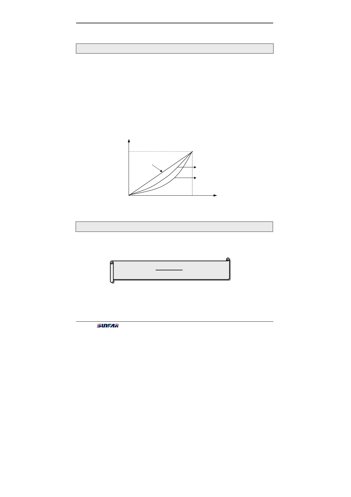
It is used for improving the low-frequency torque character. In low-frequency
running, it will make boost compensation for the output voltage of inverter, as
shown in Fig.6-5.
F1.0 Type of V/F Curve Setting range :0 ~ 3
Boost voltage = × [F1.4]
[F1.1]
100
F1.1 Torque Boost(output voltage at 0 Hz) Setting range:0 ~ 20(%)
Fig. 6-4 V/F curve
Voltage
Constant torque curve
Decreasing torque curve 1
Decreasing torque curve 2
[F1.4
]
he max
output
voltage
F. 1 .3
f