54 SUNFAR C300
C300 series of non-sensor current vector-control inverter manual
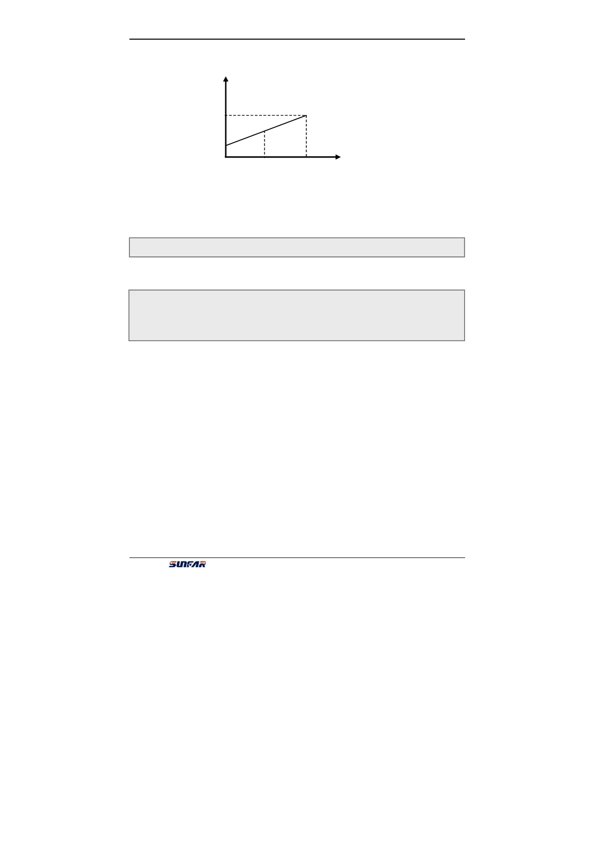
[F2.11]
AVO
Rated current
Output freq.
Upper limit voltage
[F2.10]
Output current
The max/rated Voltage
Output voltage
Rotor speed
PID setting
PID feedback
1
2
3
4
5
6
10.00
10.00
6.4
Digital O/I parameter unit
0:Control ter
1:Multi-speed control terminal 1
2:Multi-speed control terminal 2
3:Multi-speed control terminal 3
Combination of multi-speed control terminals is used for selecting output freq. of
multi-speed.
4:Wobble freq. is valid
When F7.0 is ###2 and any of those parameters are set 4, wobble freq. is valid.
5:State of wobble freq. reset
When inverter stop and F7.0 is ##0#, forcible reset will work by setting those
parameters.
6:FWD jog control
7:REV jog control
When F0.4 is ###1 and any of those parameters is set 6 or 7, external jog signal is
valid.
8:Acc& Dec time selection terminal 1
9:Acc& Dec time selection terminal 2
F3.0 Function selection of input ternimal1 Setting range:0 ~ 25
F3.1 Function selection of input ternimal2 Setting range:0 ~ 25
F3.2 Function selection of input ternimal3 Setting range:0 ~ 25
F3.3 Function selection of input ternimal4 Setting range:0 ~ 25
F2.12 Reserved
Fig.6-11 output of analog terminals