SUNFAR C300 53
C300 series of non-sensor current vector-control inverter manual
16
External voltage VC + External
current+ panel setting
17
External voltage VC + External
Current – panel setting + digital setting
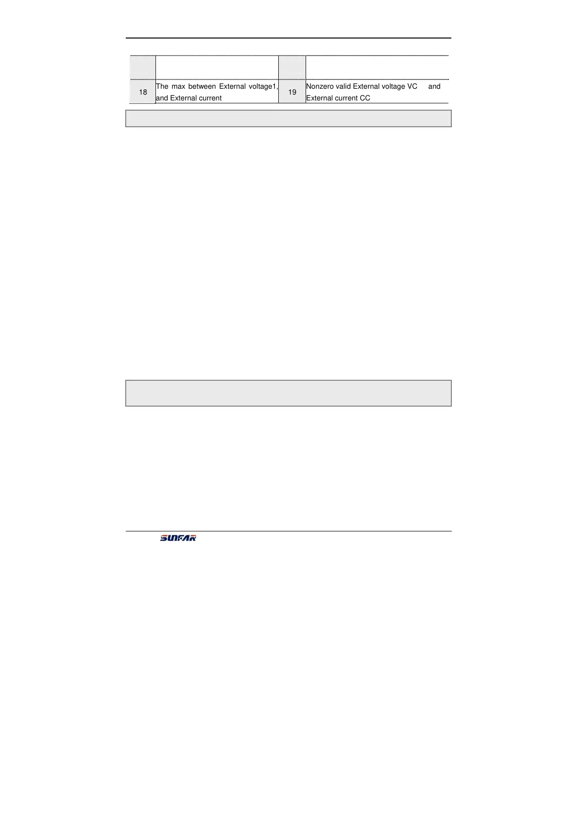
18
The max between External voltage1,
and External current
19
Nonzero valid External voltage VC and
External current CC
It defines meanings of AVO.
The first part of LED: it defines the meanings of analog output terminal AVO.
0:Output freq.
Amplitude accumulation of AVO is in direct ratio to the output frequency. F2.11 is
corresponding to the upper limit freq.
1:Output current
Amplitude accumulation of AVO is in direct ratio to the output current. F2.11 is twice
rated current of inverter.
2:Output voltage
Amplitude accumulation of AVO is in direct ratio to the output voltage. F2.11 is
corresponding to [F1.4] and [F1.15].
3:Rotational speed of applied motor
Amplitude accumulation of AVO is in direct ratio to the motor rotational speed of
inverter. F2.11 is corresponding to rotational speed that is corresponded with the
upper limit freq.
4:PID setting
Amplitude accumulation of AVO is in direct ratio to the setting value of PID. F2.11 is
corresponding to feedback of 10.00.
5:PID feedback
Amplitude accumulation of AVO is in direct ratio to the PID feedback. F2.11 is
corresponding to feedback of 10.00.
The second, third and fourth part of LED: Reserved.
Those parameters define the Maximum and minimum value of analog output
AO1and AO2, shown as fig 6-11.
F2.9 Analog output selection Setting range: 0000 ~ 0005
F2.10 the lower limit of analog output AVO Setting range: 0.0 V ~ [F2.11]
F2.11 the upper limit of analog output AVO Setting range: [F2.10] ~ 12.0 V
 Loading...
