SUNFAR C300 91
C300 series of non-sensor current vector-control inverter manual
9.5 PLC controls the startup and stop of inverter and 3-speed
operation
9.5.1 The brief introduction of example control function:
Through a simple example of PLC control inverter, the inverter achieves the aim of
integration with system under providing a typical control method. The control
approaches are as follows: 1, through terminal X0 to startup the running of inverter,
2, through terminal X5 to stop the running of inverter, 3, through the switching on
terminal X1, X2 and X3 which respectively correspond to 10Hz, 20Hz, 50Hz, and
M
Motor
U
W
V
R
S
T
Power
supply
E
RS485
A
B
Host
M
Motor
U
W
V
R
S
T
Power
supply
RS485
A
B
Guest
M
Motor
U
W
V
R
S
T
Power
supply
RS485
A
Guest
B
×
×
×
3-Phase Breaker
×
×
×
3-Phase Breaker
×
×
×
3-Phase Breaker
+5V
GND
+5V
GND
VC
VC
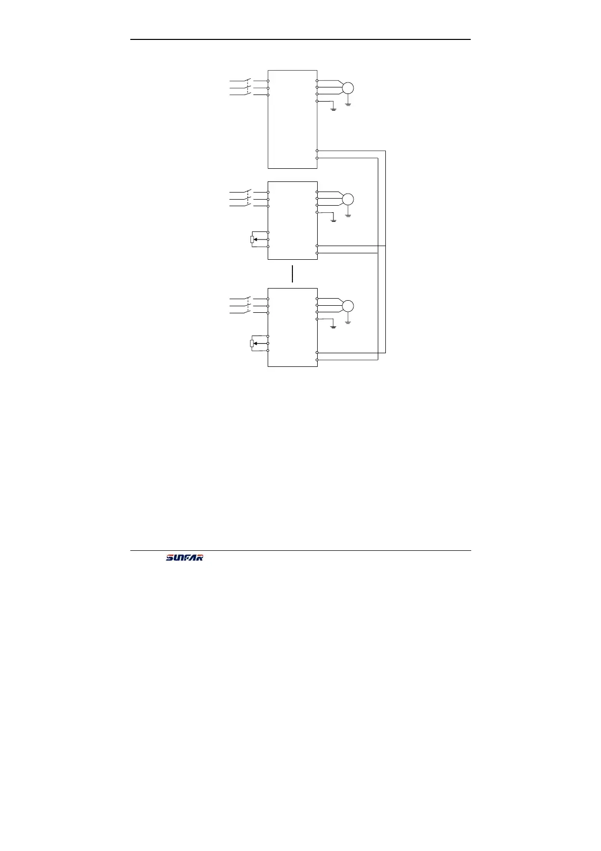
Fig9-4 Basic wiring