92 SUNFAR C300
C300 series of non-sensor current vector-control inverter manual
the output frequency is invalid ( the output frequency is 0 ) if these terminals switch
on simultaneously.
9.5.2 The system configuration:
Main site: MITSUBISHI PLC Model: FX2N-16MR-001
Subordinative site: C300-2S0022 series of inverter
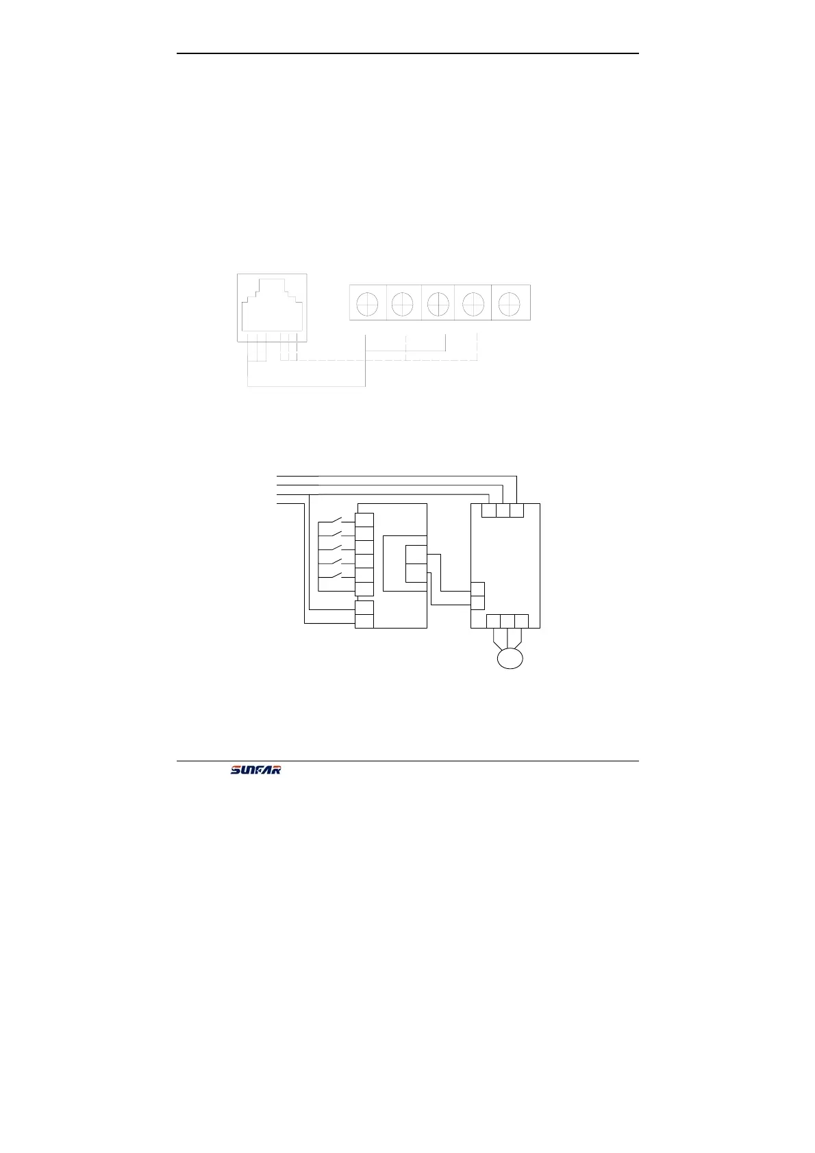
9.5.3 The connection of master and slave hardware:
SUNFAR inverter uses crystal pin telephone line to connect PLC, using RS485.
Please refer to the following fig9-5.
9.5.4 The master control wiring diagram of SUNFAR inverter and PLC:
9.5.5 The slave setting:
1, The channels of output frequency: communication interface(F0.1=2)
+ + + - - -
水晶插座
RDA RDB
SDA SDB SG
Fig 9-5 Wiring method
N
L
COM
X0
X1
X2
X3
X5
stop
Speed
3
Speed
2
Speed
1
start
FX2N
-485
-BD
RDA
RDB
R S T
U V W
+
-
M
Three-
phase
power grid
C300
FX2N
Fig 9-6 Main circuit wiring