SUNFAR C300 9
C300 series of non-sensor current vector-control inverter manual
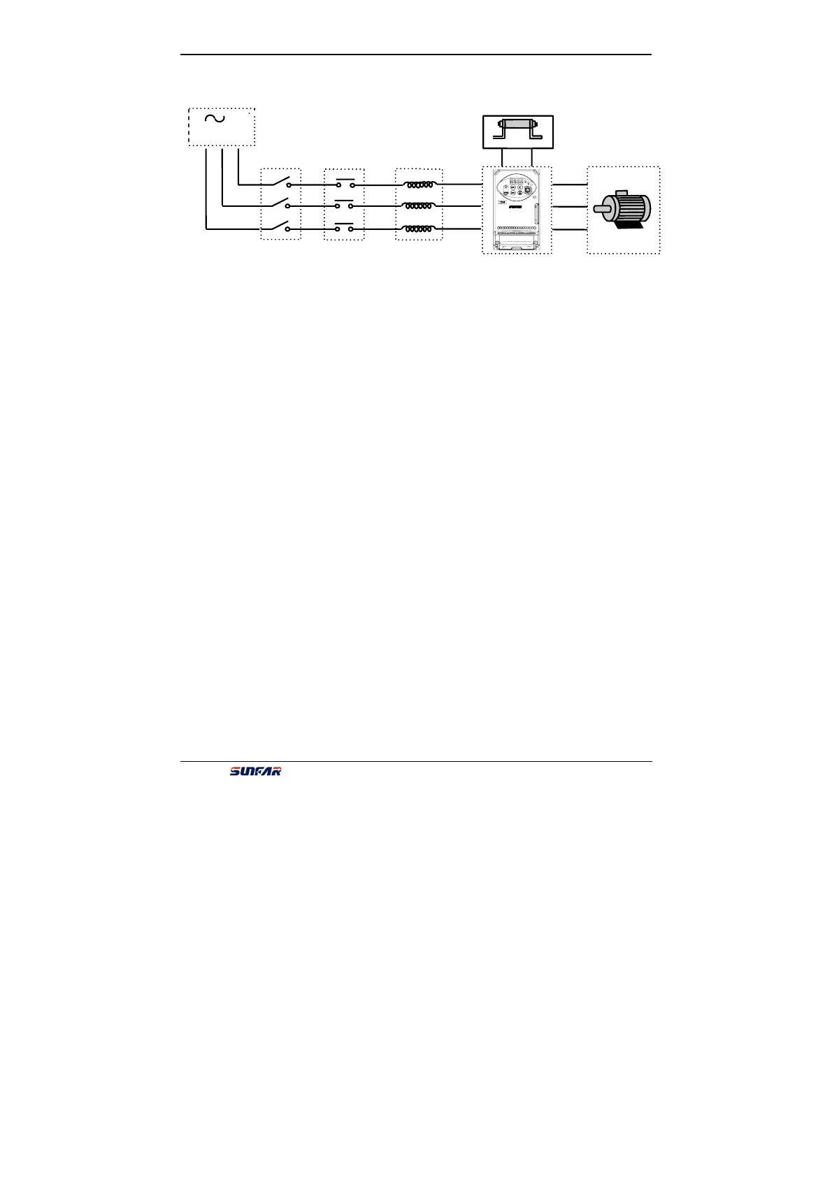
3.2 Wiring of External Components
z Power Supply
It is according to the rated input power specifications in manual.
z Air-break switch
1. When the inverter is in maintenance or leave-unused, the air-break switch should
isolate the inverter from power supply.
2. Input side of inverter takes place the fault of short-circuits or low-voltage, the
air-break would take the protection.
z Contactor
Control the power-on or power-off of inverter expediently.
z AC electric reactor
1. Improve the power factor.
2. Reduce the harmonic wave input for the electric network.
3. Weaken the imbalance effect on 3-phase power voltage.
z Brake resistor
In situation of the regenerative braking, avoiding bringing voltage too highly.
R / L1
S / L2
T
U
V
W
C300
P+
PB
Fig.3-2 wiring
1. Refer to the instruction manual before installation
and operation.
2. DO not connect AC power to output terminals
UVW.
3. Isolate from supply and wait 10 minutes before
removing this cover.
4. Securely ground(earth) the equipment.
CAUTION
ir Breaker Switch
Circuit
Breaker
AC Electric
Reactor
Motor
C Powe