72 SUNFAR C300
C300 series of non-sensor current vector-control inverter manual
6.9 PID control parameter unit
The first part of LED(form right to left): Inner PID control
0:Inner PID control is invalid 1:Inner PID control is valid
2:Inner PID control is conditional valid. Inner PID is set by external terminals X1~
X4 ( Parameters F3.0~F3.3) .
The second part of LED: PID controller selection
0: proportion 1:Integral 2:Proportion and integral
The third part of LED: Regulating property of PID controller
0: positive interaction 1:Reactor
The fourth part of LED: The pole choosing of PID controller
0: Monopole PID control 1: ambipolar PID control
Under the monopole PID control mode, the output phase sequence of inverter is
mono-direction; and the external terminal decides the direction of output that it has
no relation with the output of PID controller. The adjusting effect of PID controller
F8.0 Inner PID control Setting range:0000 ~ 1122
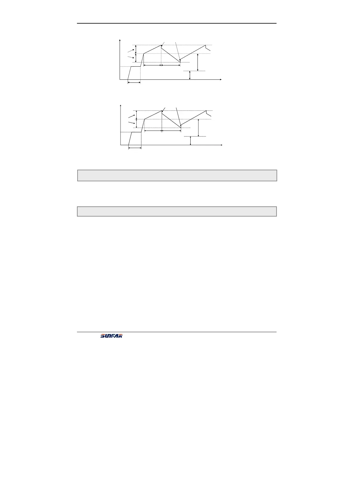
F7.2
External freq. set by [F0.1]
Preset center freq. of wobble freq.
[F7.7]
mplitude o
wobble freq.
[F7.1]
[F7.4] ×Amplitude of wobble freq.
[F7.5] [F7.6]
Running freq.
t
Fig.6-27 running process of wobble freq.
6-28 Running process of wobble freq.
F7.8 Reserved
F7.2
External freq. set by [F0.1]
Preset center freq. of wobble freq.
[F7.7]
mplitude o
wobble freq.
[F7.1]
[F7.4] ×Amplitude of wobble freq.
[F7.5] [F7.6]
Running freq.
t