SUNFAR C300 73
C300 series of non-sensor current vector-control inverter manual
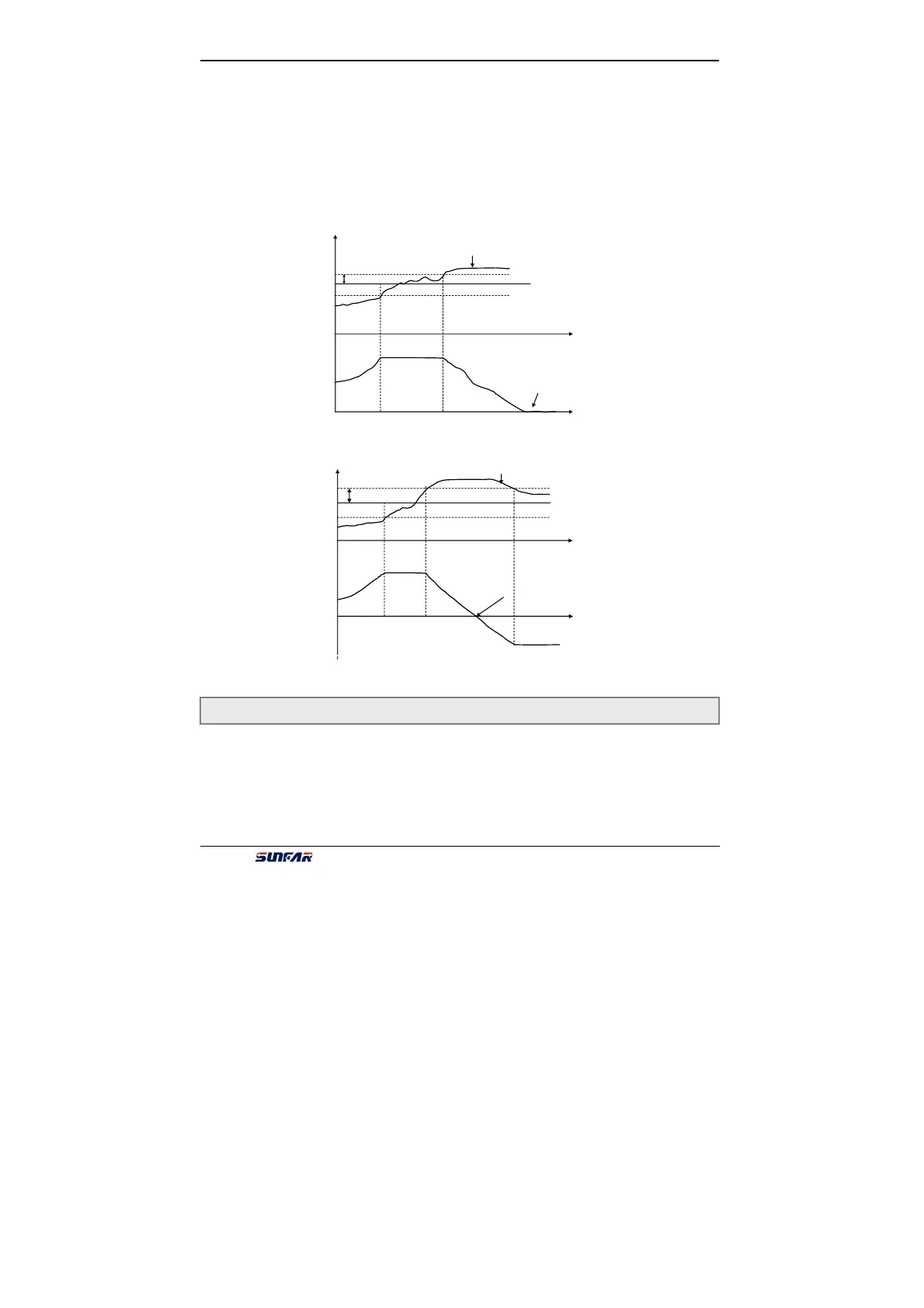
only affect the output frequency of inverter. Please refer to fig 6-29.
Monopole PID control applies in water and voltage supply which do not need the
setting of motor’s reversion.
Under the ambipolar PID control mode, when the adjusting effect of PID controller
makes the output frequency as 0, and it has margin between PID setting and
feedback, the output phase sequence and motor’s reversion would change. That is
to say, the external terminal and PID controller decide the motor’s reversion
together under this control mode. Please refer to fig 6-30.
It is used for setting inner PID and feedback channel.
The first part of LED(form right to left):It is used for setting PID channel .
0:Digital setting. It is set by parameter F8.2.
1:Serials interface setting
2:Panel potentiometer setting, it is on the operation panel.
F8.1 Inner PID setting and channel selection Setting range:0000 ~ 0504
PID setting
Time
Time
warp limit [F8.9]
PID feedback
Output frequency
Under monopole PID
control mode, when
output frequency reduces
to o, the direction would not
change.
Fig 6-29 Monopole PID control mode
Time
Time
Warp limit [F8.9]
Output frequency
PID feedback
Under the ambipolar
PID control mode,,the
output frequency would
change the phase
sequence
Fig 6-30 Ambipolar PID control mode