SUNFAR C300 19
C300 series of non-sensor current vector-control inverter manual
5. PARAMETERS LIST
means that this parameter can not be changed during operation.★
▲ means that this parameter is related to the inverter’s model.
Parameters’
Types
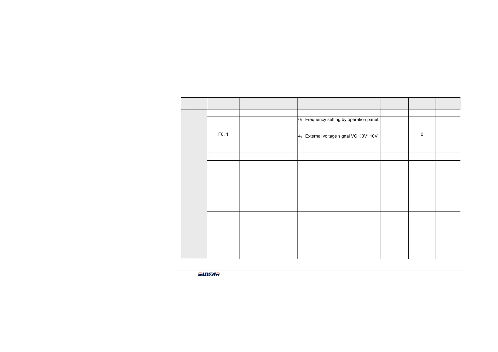
Function Code Name Setting range
Minimum
Setting
Manufacture
Setting
Modify
Limit
F0. 0 Control methods 0:V/F method; 1:Vector control 1 1 ★
F0. 1
Frequency input channel
/ mode selection
0:Frequency setting by operation panel
1:UP/DW Acc and Dec control
2:RS485 interface
3:Panel potentiometer
4:External voltage signal VC(0V~10V)
5:External current signal CC(0~20mA)
6:Combination setting
7:External terminals
1 0
F0. 2 Frequency digital setting 0.00 ~ the upper limit frequency 0.01 0
F0. 3
Auxiliary control
of freq. digital
setting
The first part of LED(form right to left):
0 : Setting freq. will save after power
down
1:Setting freq. will not save after power
down
The second part of LED:
0:Setting freq. is keep when stopping
1:Setting freq. will save in F0.2 when
stopping
2:Setting freq. isclear when stopping
The third and fourth part of LED(form
right to left):Reserved
1 0000
Basic operation parameter unit
F0. 4
Operation
Channel selection
The first part of LED (form right to left):
0:Panel control
1:External terminals
2:RS485 interface
The second part ofLED:Function of key
STOP
0:It is valid for panel control.
1:It is valid for all kinds of control
method.
The third and fourth part of LED(form
right to left):Reserved
1 0000