SUNFAR C300 47
C300 series of non-sensor current vector-control inverter manual
f
V
[F1.6]
[F1.8]
[F1.10]
[F1.1]
[F1.9]
[F1.7]
[F1.5]
[F1.4]
[F1.3]
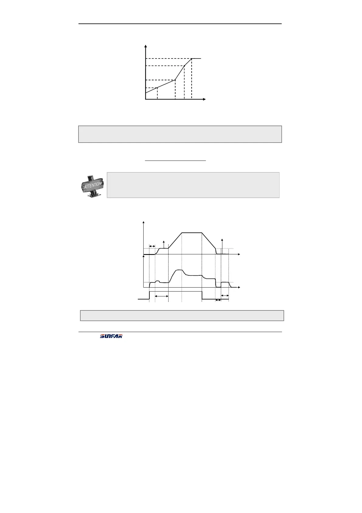
as Fig.6-6:
Those parameters are fit for the occasion that inverter need brake before start.
Parameter F1.12 defines duration time that inverter output DC braking current.
When F1.12 is 0, DC braking is invalid when start. Shown as Fig.6-7.
Fig.6-6 V/Fuser-defined curve
F1.13 Reserved
F1.11 DC braking current when start Setting range:0.0 ~ 100.0 (%)
F1.12 DC braking time when start Setting range:0.0 ~ 20.0 S
When rated current of motor is lower than rated current of inverter, please pay
attention to set F1.11.Make sure that DC braking current is lower than rated
current of motor.
Fig.6-7 Process of start and stop
F1.11=
DC braking current when starting
Rated current of inverter
×
100%
Output Freq.
Instruction
Starting
fre
.
[F4.4]
DC braking
[F4.1]
[F1.11
]
Output
current
[F4.7]
[
F4.6]
[
F4.5]
[
F4.2]
[
F1.12]
 Loading...
