50 SUNFAR C300
C300 series of non-sensor current vector-control inverter manual
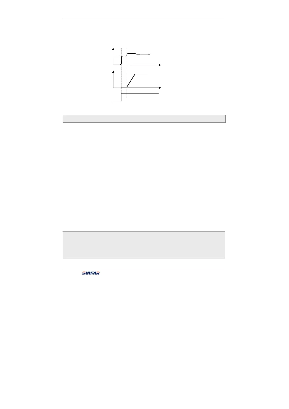
Current
Output freq.
[F1.22]
[F1.19]
When inverter is running, it will output excitation current even the freq. output is 0.
So there is no pre-excitation of starting time when start-up motor.
The second and third part of LED (form right to left) reserved.
It is used for selecting self-adapting rectify of motor parameters function(set by
binary system).
The first part of LED (form right to left): to select self-adapting rectify of stator
resistance function
0:Self-adapting rectify of stator resistance is invalid
1:Self-adapting rectify of stator resistance is valid
The second part of LED (form right to left): to select self-adapting rectify of
excitation function
0:Self-adapting rectify of excitation is invalid
1:Self-adapting rectify of excitation is valid
The third part of LED (form right to left): to select self-adapting rectify of rotor
resistance function
0:Self-adapting rectify of rotor resistance is invalid
1:Self-adapting rectify of rotor resistance is valid
The fourth part of LED (form right to left): reserved.
Some parameters of motor have influenced by temperature change, and control
performance is affected if setting value isn’t precision. When motor have selected
corresponding function, inverter will optimize parameters automatically in running,
which can improve the performance and stability of motor.
F1.23 Self-adapting rectify of motor parameters Setting range: 0000 ~ 0111
Fig. 6-9 TO start pre-excitation
F1.24 stator resistance Setting range: 0.000 ~ 20.000 (Ω)
F1.25 rotor resistance Setting range: 0.000 ~ 20.000 (Ω)
F1.26 rotor inductance Setting range: 0.00 ~ 600.00 (mH)
F1.27 excitation inductance Setting range: 0.00 ~ 600.00 (mH)
F1.28 Leakage inductance (coefficient) Setting range: 0.00 ~ 100.00 (mH)