6 Electrical Connection User Manual
24
Different device types must connect to different RS485 communication ports of
the Logger1000. For example, connect the transformer and inverter to different
RS485 communication ports of the Logger1000.
The addresses of devices on each RS485 bus must be different from one another
and within the address range set for the Logger1000 (address range of residential
inverters and string inverters manufactured by SUNGROW: 1-247; address range
of third-party devices: 1-255). Otherwise, communication error will occur.
Serial port parameters of each device on the RS485 bus should be consistent
with those of the Logger1000. The serial port parameters include baud rate, data
bit, stop bit, and check bit.
6.3.2 Connection to Energy Meter
It is recommended to use the energy meter whose communication protocol
complies with DL/T645-2007 protocol or Modbus RTU protocol. The recommended
energy meter types are as follows:
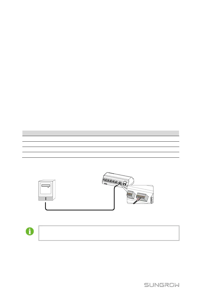
The following figure shows the connection between the Logger1000 and the energy
meter.
Connect the communication cable led from the energy meter to the RS485 port of
the Logger1000.
All devices on each RS485 bus support the same communication
protocol.
6.3.3 Connection to Meteo Station
The following figure shows the connection between the Logger1000 and the Meteo
Station.