6 Electrical Connection User Manual
28
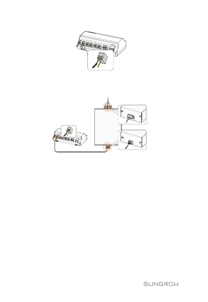
Step 4 Connect the DC cable led from the "24V IN" port of the Logger1000 to the
"DC 24V OUT" port of the power box. Connect the stripped AC cable to the
"AC (100~277V)" port of the power box, and connect the other end of the AC
cable to the 220V AC power.
Logger1000 Power box
DC 24V OUT
AC (100~277V)
6.7 Cable Routing Requirements
Cables used in the system generally include power cables and communication
cables.
The communication cable needs to be routed away from the power cable, and the
cables need to form a right angle at the intersection. The communication cable
needs to be as short as possible and keeps a distance from the power cable.
Power cables and communication cables should be routed in different cable
trenches to avoid long-distance parallel cable routing of power cables and other
cables, thereby reducing electromagnetic interference due to output voltage
transient.
The distance between the power cable and communication cable should be greater
than 200mm. When the cables meet with each other, the cross angle should be 90°,
and the distance can be reduced accordingly.
The following table shows the recommended minimum distances between parallel