User Manual 6 Electrical Connection
27
Tab. 6-2 Power cable specification
Cable
Recommended
cross-section
jacket
Length of
insulation to be
stripped off
1mm
2
~1.5mm
2
15mm 8mm~10mm
1mm
2
~1.5mm
2
8mm~10mm -
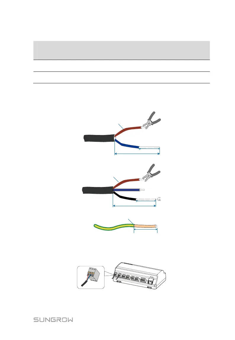
Power cable wiring steps are as follows:
Step 1 Strip the cable jackets and insulation layers of the DC cable, AC cable, and
grounding cable with a wire stripper by appropriate length.
1mm
2
~
1.5 mm
2
A
A:15mm
B:8mm
~
10mm
B
DC cable
AC cable
A
A:15mm
B:8mm
~
10mm
B
1mm
2
~
1.5 mm
2
L
N
A
1mm
2
~
1.5mm
2
A:8mm
~
10mm
Grounding cable
Step 2 Insert the stripped DC cable into the "24V IN" and "24V OUT" ports of the
Logger1000. Connect the DC cable led from the "24V OUT" port of the
Logger1000 to other devices that need 24V DC power supply.
Step 3 Connect the stripped grounding cable to the corresponding port of the
Logger1000.