6 Electrical Connection User Manual
20
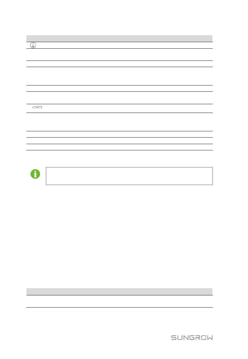
Connecting protective grounding cable
AI/DI
Compatible with AI/DI
function
Default AI input sampling: 0-10V or
4-20mA
DRM
Response Modes)
Works together with the DI1~DI4 to
achieve the DRM function
RS485
Support of 3 inputs of RS485
SIM card slot Support of Micro-SIM card
ETH Ethernet port
Can be connected to background master
via devices such as Ethernet switch and
Press it for 3s to restart
Note: * Only the Logger1000A is equipped with the SIM card slot and the 4G
function.
1
1
3
3
) ports, the communication distance should not
exceed 1,000m.
6.3 Connection to PV Devices
Devices in the PV system that can be connected to the Logger1000 include the
inverter, Meteo Station, energy meter, etc.
6.3.1 Connection to Inverter
Connection to a single inverter
The RS485 port of SUNGROW inverter is RS485 terminal block or RJ45 port.
RS485 terminal block connection
Communication cable specification:
Recommended cross-section
RS485 communication
cable
Shielded twisted pair 0.75mm
2
~1.5mm
2